8.5 Installing Peripheral Devices
380 YASKAWA ELECTRIC SIEP C710616 27C YASKAWA AC Drive A1000 Technical Manual
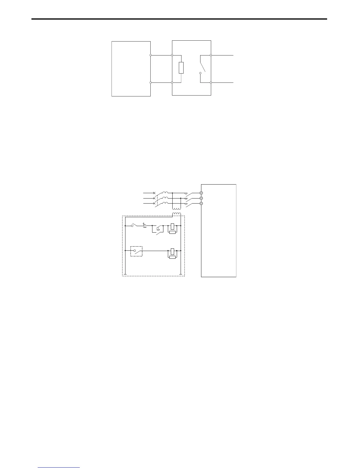
Figure 8. 6
Figure 8.6 Connecting a Braking Resistor Unit: LKEB Type
(CIMR-A2A0004 to 0138, 4A0002 to 0072)
■ Installing Other Types of Braking Resistors
When installing braking resistors other than the ERF or LKEB types, make sure that the drive internal braking transistor
will not be overloaded with the required duty cycle and the selected resistance value. Use a resistor that is equipped with
a thermal overload relay contact, and utilize this contact to switch off the drive in case of braking resistor overheat.
■
Braking Resistor Overload Protection
If using a braking resistor option, a sequence such as the one shown in Figure 8.7 should be set up to interrupt the power
supply in case the braking resistor overheats.
Figure 8. 7
Figure 8.7 Power Supply Interrupt for Overheat Protection (Example)
■ Installing a Braking Unit: CDBR Type
To install a CDBR type braking unit, connect the drive’s B1 terminal (units CIMR-2A0004 through 0138 and CIMR-
4A0002 through 0072) or +3 terminal (units CIMR-A2A0169 to 0211 and CIMR-A4A0088 to 0165) to the positive
terminal on the braking unit. Next wire the negative terminals on the drive and braking unit together. Terminal +2 is not
used.
Connect the braking resistor to the CDBRs terminals +0 and -0.
Wire the thermal overload relay contact of the CDBR and the braking resistor in series, and connect this signal to a drive
digital input. Use this input to trigger a fault in the drive in case a CDBR or braking resistor overload occurs.
Disable dynamic braking transistor protection by setting L8-55 = 0.

 Loading...


