■ T2-16: PG Number of Pulses Per Revolution for PM Motor Tuning
Enter the number of pulses from the PG encoder per motor rotation. Set the actual number of pulses for one full motor
rotation.
■
T2-17: Encoder Z-Pulse Offset (Δθ)
Sets the amount of compensation or offset in 0.1 degree units in order to fine-tune the home position. If the amount of
offset needed for the Z pulse is unknown or if the PG encoder is replaced, perform Z pulse tuning.
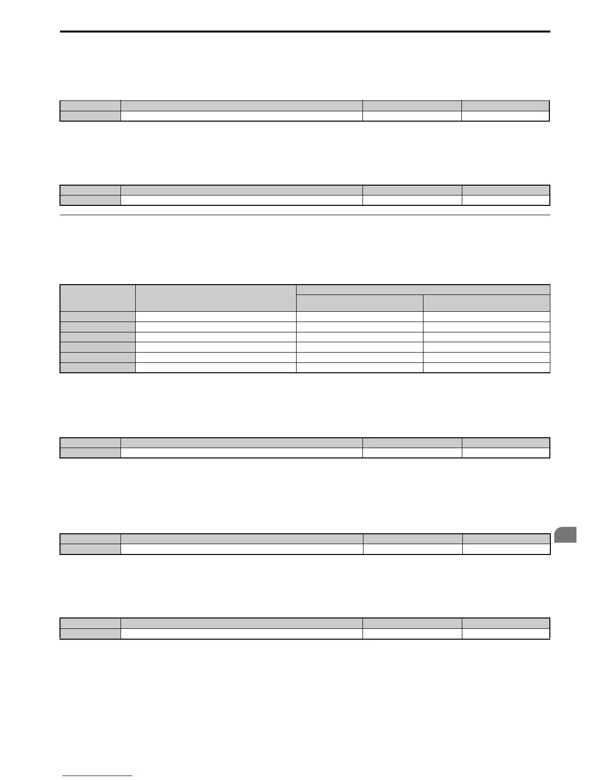
◆ Parameter Settings during Inertia and Speed Control Loop Auto-Tuning: T3
These tuning methods apply a sine wave test signal to the system. By the measuring the response the drive estimates the
system inertia. It automatically sets parameters listed in Table 4.26.
Table 4.26 Parameters Adjusted by Inertia and Speed Loop Auto-Tuning
■ T3-01: Inertia Tuning Frequency Reference
Sets the frequency of the test signal applied to the motor during Inertia Tuning. Although this setting rarely needs to be
changed, increasing the value may be beneficial when working with high inertia loads.
■
T3-02: Inertia Tuning Reference Amplitude
Enter the amplitude of the test signal applied to the motor during Inertia Tuning. Although this setting rarely needs to be
changed, try decreasing the value if the load inertia is too large and causes problems during Inertia Tuning. If a fault
occurs when T3-01 is set to low value, the situation may be remedied by adjusting T3-02.
■
T3-03: Motor Inertia
Enter the inertia of the motor. This value is used to determine the load inertia using the test signal response. The default
setting is for a Yaskawa standard motor as listed in the motor inertia table.
Note: The display resolution depends on the rated output power of the drive after the Drive Duty has been set in parameter C6-01.
Drives with a maximum output up to 37 kW will display this value in units of 0.0001 kgm
2
. Drives with a maximum output 37 to
185 kW will display this value in units of 0.001 kgm
2
. Refer to A1000 Model Selection on page 27 for details.
No. Name Setting Range Default
T2-16 PG Number of Pulses Per Revolution for PM Motor Tuning 0 to 60000 ppr 1024 ppr
No. Name Setting Range Default
T2-17 Encoder Z-Pulse Offset -180.0 to 180.0 deg 0.0 deg
Parameter Description
T1-01 or T2-01
8
Inertia Tuning
9
Speed Control Loop (ASR) Tuning
C5-01 ASR Proportional Gain 1 N/A YES
C5-17 (C5-37) Motor Inertia YES YES
C5-18 (C5-38) Motor Inertia Ratio YES YES
L3-24 Motor Acceleration Time for Inertia Calculations YES YES
L3-25 Load Inertia Ratio YES YES
n5-03 Feed Forward Control Ratio Gain YES YES
No. Name Setting Range Default
T3-01 Inertia Tuning Frequency Reference 0.1 to 20.0 Hz 3.0 Hz
No. Name Setting Range Default
T3-02 Inertia Tuning Reference Amplitude 0.1 to 10.0 rad 0.5 rad
No. Name Setting Range Default
T3-03 Motor Inertia
0.0001 to 600.00 kgm
2
Depending on E2-11

 Loading...


