Example 3: To have an output signal of 3 V at terminal FM when the monitored value is at 0%, set H4-03 to 30%.
Figure 5.84
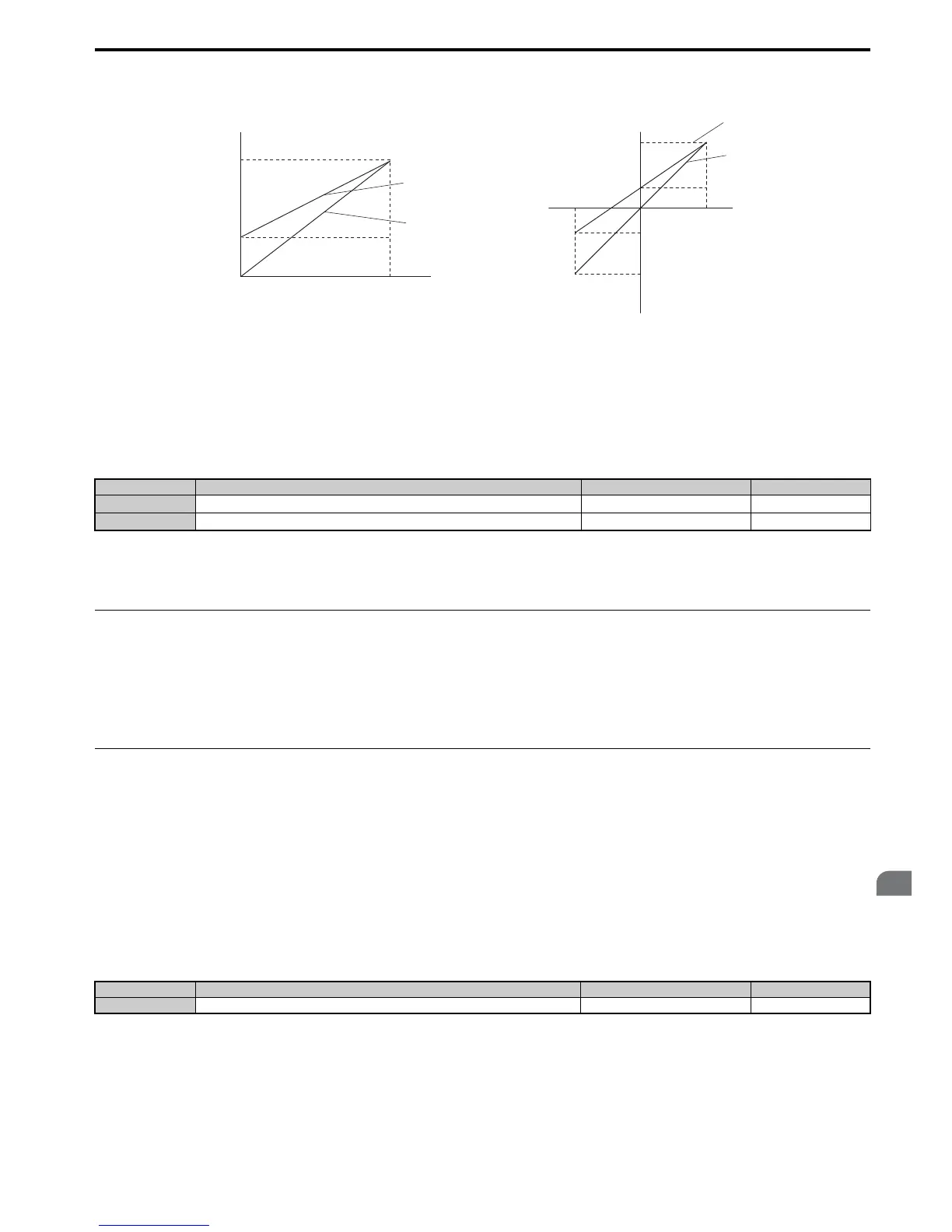
Figure 5.84 Analog Output Gain and Bias Setting Example 3
■ H4-07, H4-08: Multi-Function Analog Output Terminal FM, AM Signal Level Selection
Sets the voltage output level of U parameter (monitor parameter) data to terminal FM and terminal AM using parameters
H4-07 and H4-08.
When changing the setting of these parameters make sure jumper S5 on the terminal board is set accordingly. Refer to
Terminal AM/FM Signal Selection on page 79 for details on setting S5.
Setting 0: 0 to 10 V
Setting 1: -10 V to 10 V
Setting 2: 4 to 20 mA
◆ H5: MEMOBUS/Modbus Serial Communication
Through the drives built in RS-422/485 port (terminals R+, R-, S+, S-), serial communication is possible using
programmable logic controllers (PLCs) or similar devices running the MEMOBUS/Modbus protocol.
The H5- parameters are used to set up the drive for MEMOBUS/Modbus Communications. Refer to MEMOBUS/
Modbus Serial Communication on page 482 for detailed descriptions of the H5- parameters.
◆ H6: Pulse Train Input/Output
A one track pulse train signal with a maximum frequency of 32 kHz can be input to the drive at terminal RP. This pulse
train signal can be used as the frequency reference, for PID functions, or as the speed feedback signal in V/f Control.
The pulse output monitor terminal MP can output drive monitor values as a pulse train signal with a maximum frequency
of 32 kHz. It can be used in sinking or sourcing mode. Refer to Using the Pulse Train Output on page 78 for details.
Use parameters H6- to set the scale and other aspects of the pulse input terminal RP and pulse output terminal MP.
■
H6-01: Pulse Train Input Terminal RP Function Selection
Selects the function of pulse train input terminal RP.
Setting 0: Frequency reference
If the pulse input is set for this function and the frequency reference source is set to pulse input (b1-01, b1-15 = 4), the
drive reads the frequency value from terminal RP.
No. Name Setting Range Default
H4-07
Multi-Function Analog Output Terminal FM Signal Level Selection
0 to 2 0
H4-08
Multi-Function Analog Output Terminal AM Signal Level Selection
0 to 2 0
No. Name Setting Range Default
H6-01 Pulse Train Input Terminal RP Function Selection 0 to 3 0

 Loading...


