56 YASKAWA ELECTRIC SIEP C710616 27C YASKAWA AC Drive A1000 Technical Manual
3.3 Main Circuit Connection Diagram
3.3 Main Circuit Connection Diagram
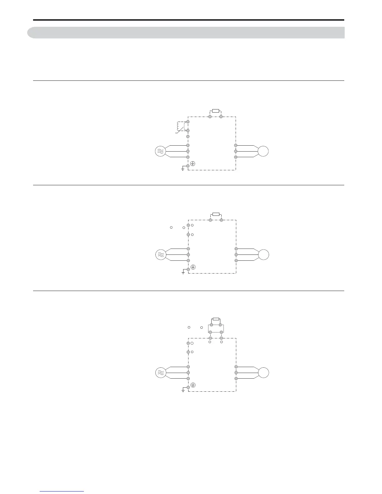
Refer to diagrams in this section when wiring the drive’s main circuit. Connections may vary based on drive capacity.
The DC power supply for the main circuit also provides power to the control circuit.
NOTICE: Do not use the negative DC bus terminal “-” as a ground terminal. This terminal is at high DC voltage potential. Improper
wiring connections could damage the drive.
◆ Three-Phase 200 V Class (CIMR-A2A0004 to 0081)
Three-Phase 400 V Class (CIMR-A4A0002 to 0044)
Figure 3. 5
Figure 3.2 Connecting Main Circuit Terminals
◆ Three-Phase 200 V Class (CIMR-A2A0110, 0138)
Three-Phase 400 V Class (CIMR-A4A0058, 0072)
Figure 3. 6
Figure 3.3 Connecting Main Circuit Terminals
◆ Three-Phase 200 V Class (CIMR-A2A0169 to 0415)
Three-Phase 400 V Class (CIMR-A4A0088 to 0675)
Figure 3. 7
Figure 3.4 Connecting Main Circuit Terminals
Braking Resistor Unit
(option)
Drive
Motor
Jumper
DC reactor
(option)
B1
+1
R/L1
S/L2
T/L3
U/T1
V/T2
W/T3
+2
−
B2
3 Phase power supply
200 to 240 V
ac, 50 to 60 Hz
380 to 480 Vac, 50 to 60 Hz
+3
R/L1
S/L2
T/L3
U/T1
V/T2
W/T3
Braking Unit
(option)
Braking Resistor Unit
(option)
Drive
Motor
−
−
Use terminals and
for DC power supply
+1
−
3 Phase power supply
200 to 240 Vac, 50 to 60 Hz
380 to 480 Vac, 50 to 60 Hz
+1

 Loading...


