B.3 Parameter Table
434 YASKAWA ELECTRIC SIEP C710616 27C YASKAWA AC Drive A1000 Technical Manual
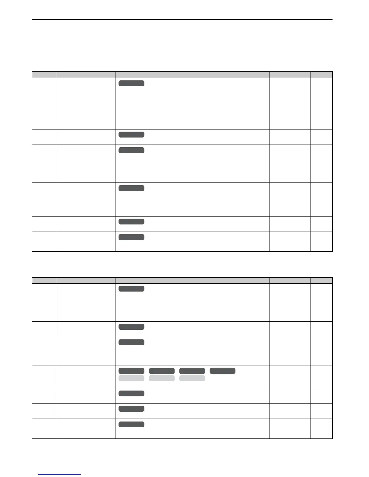
◆ L: Protection Function
L parameters provide protection to the drive and motor, such as: control during momentary power loss, Stall Prevention,
frequency detection, fault restarts, overtorque detection, torque limits, and other types of hardware protection.
■
L1: Motor Protection
■ L2: Momentary Power Loss Ride-Thru
No. (Addr.) Name Description Setting Page
L1-01
(480H)
<10> Default setting is determined by the control mode (A1-02).
Motor Overload Protection
Selection
0: Disabled
1: General purpose motor (standard fan cooled)
2: Drive dedicated motor with a speed range of 1:10
3: Vector motor with a speed range of 1:100
4: PM motor with variable torque
5: PM motor with constant torque control
6: General purpose motor (50 Hz)
The drive may not be able to provide protection when multiple motors are used, even if
overload is enabled in L1-01. Set L1-01 to 0 and install separate thermal relay to each motor.
Default:
<10>
Min: 0
Max: 6
244
L1-02
(481H)
Motor Overload Protection Time
Sets the motor thermal overload protection (oL1) time.
Default: 1.0 min
Min: 0.1 min
Max: 5.0 min
246
L1-03
(482H)
Motor Overheat Alarm Operation
Selection (PTC input)
Sets operation when the motor temperature analog input (H3-02, H3-06, or H3-10 = E) exceeds
the oH3 alarm level.
0: Ramp to stop
1: Coast to stop
2: Fast Stop (decelerate to stop using the deceleration time in C1-09)
3: Alarm only (“oH3” will flash)
Default: 3
Min: 0
Max: 3
248
L1-04
(483H)
Motor Overheat Fault Operation
Selection (PTC input)
Sets stopping method when the motor temperature analog input (H3-02, H3-06, or H3-10 = E)
exceeds the oH4 fault level.
0: Ramp to stop
1: Coast to stop
2: Fast Stop (decelerate to stop using the deceleration time in C1-09)
Default: 1
Min: 0
Max: 2
248
L1-05
(484H)
Motor Temperature Input Filter
Time (PTC input)
Adjusts the filter for the motor temperature analog input (H3-02, H3-06, or H3-10 = E).
Default: 0.20 s
Min: 0.00 s
Max: 10.00 s
248
L1-13
(46DH)
Continuous Electrothermal
Operation Selection
0: Disabled
1: Enabled
Default: 1
Min: 0
Max: 1
248
No. (Addr.) Name Description Setting Page
L2-01
(485H)
Momentary Power Loss Operation
Selection
0: Disabled. Drive trips on (Uv1) fault when power is lost.
1: Recover within the time set in L2-02. Uv1 will be detected if power loss is longer than L2-02.
2: Recover as long as CPU has power. Uv1 is not detected.
3: KEB deceleration for the time set to L2-02.
4: KEB deceleration as long as CPU has power.
5: KEB deceleration to stop.
Default: 0
Min: 0
Max: 5
249
L2-02
(486H)
Momentary Power Loss Ride-Thru
Time
Sets the Power Loss Ride-Thru time. Enabled only when L2-01 = 1 or 3.
Default:
<9>
Min: 0.0 s
Max: 25.5 s
254
L2-03
(487H)
Momentary Power Loss Minimum
Baseblock Time
Sets the minimum wait time for residual motor voltage decay before the drive output
reenergizes after performing Power Loss Ride-Thru.
Increasing the time set to L2-03 may help if overcurrent or overvoltage occur during Speed
Search or during DC Injection Braking.
Default:
<9>
Min: 0.1 s
Max: 5.0 s
254
L2-04
(488H)
Momentary Power Loss Voltage
Recovery Ramp Time
Sets the time for the output voltage to return to the preset V/f pattern during Speed Search.
Default:
<9>
Min: 0.0 s
Max: 5.0 s
254
L2-05
(489H)
Undervoltage Detection Level
(Uv)
Sets the DC bus undervoltage trip level.
Default:
<18> <33>
Min: 150 Vdc
Max: 210 Vdc
<18>
254
L2-06
(48AH)
KEB Deceleration Time
Sets the time required to decelerate from the speed when KEB was activated to zero speed.
Default: 0.00 s
Min: 0.00 s
Max: 6000.0 s
<12>
254
L2-07
(48BH)
KEB Acceleration Time
Sets the time to accelerate to the frequency reference when momentary power loss is over. If set
to 0.0, the active acceleration time is used.
Default: 0.00 s
Min: 0.00 s
Max: 6000.0 s
<12>
254
All Modes

 Loading...


