524 YASKAWA ELECTRIC SIEP C710616 27C YASKAWA AC Drive A1000 Technical Manual
E.3 User Setting Table
E.3 User Setting Table
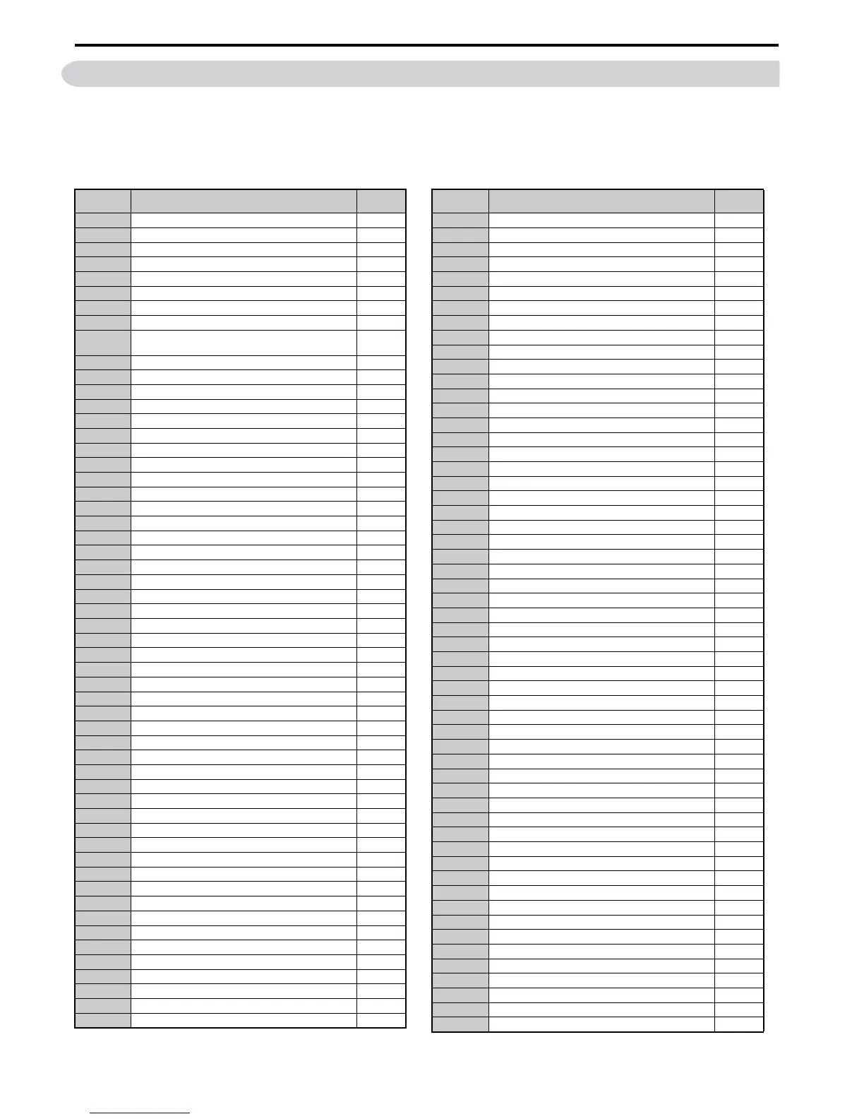
Use the Verify Menu to see which parameters have been changed from their original default settings.
• The diamond below the parameter number indicates that the parameter setting can be changed during run.
• Parameter names in boldface type are included in the Setup Group of parameters.
No. Name
User
Setting
A1-00 Language Selection
A1-01 Access Level Selection
A1-02 Control Method Selection
A1-03 Initialize Parameters
A1-04 Password
A1-05 Password Setting
A1-06 Application Preset
A1-07 DriveWorksEZ Function Selection
A2-01 to
A2-32
User Parameters 1 to 32
A2-33 User Parameter Automatic Selection
b1-01 Frequency Reference Selection 1
b1-02 Run Command Selection 1
b1-03 Stopping Method Selection
b1-04 Reverse Operation Selection
b1-05 Action Selection below Minimum Output Frequency
b1-06 Digital Input Reading
b1-07 LOCAL/REMOTE Run Selection
b1-08 Run Command Selection while in Programming Mode
b1-14 Phase Order Selection
b1-15 Frequency Reference Selection 2
b1-16 Run Command Selection 2
b1-17 Run Command at Power Up
b2-01 DC Injection Braking Start Frequency
b2-02 DC Injection Braking Current
b2-03 DC Injection Braking Time at Start
b2-04 DC Injection Braking Time at Stop
b2-08 Magnetic Flux Compensation Value
b2-12 Short Circuit Brake Time at Start
b2-13 Short Circuit Brake Time at Stop
b2-18 Short Circuit Braking Current
b3-01 Speed Search Selection at Start
b3-02 Speed Search Deactivation Current
b3-03 Speed Search Deceleration Time
b3-04 V/f Gain during Speed Search
b3-05 Speed Search Delay Time
b3-06 Output Current 1 during Speed Search
b3-10 Speed Search Detection Compensation Gain
b3-14 Bi-Directional Speed Search Selection
b3-17 Speed Search Restart Current Level
b3-18 Speed Search Restart Detection Time
b3-19 Number of Speed Search Restarts
b3-24 Speed Search Method Selection
b3-25 Speed Search Wait Time
b4-01 Timer Function On-Delay Time
b4-02 Timer Function Off-Delay Time
b5-01 PID Function Setting
b5-02 Proportional Gain Setting (P)
b5-03 Integral Time Setting (I)
b5-04 Integral Limit Setting
b5-05 Derivative Time (D)
b5-06 PID Output Limit
b5-07 PID Offset Adjustment
b5-08 PID Primary Delay Time Constant
b5-09 PID Output Level Selection
b5-10 PID Output Gain Setting
No. Name
User
Setting
b5-11 PID Output Reverse Selection
b5-12 PID Feedback Loss Detection Selection
b5-13 PID Feedback Loss Detection Level
b5-14 PID Feedback Loss Detection Time
b5-15 PID Sleep Function Start Level
b5-16 PID Sleep Delay Time
b5-17 PID Accel/Decel Time
b5-18 PID Setpoint Selection
b5-19 PID Setpoint Value
b5-20 PID Setpoint Scaling
b5-34 PID Output Lower Limit
b5-35 PID Input Limit
b5-36 PID Feedback High Detection Level
b5-37 PID Feedback High Detection Time
b5-38 PID Setpoint User Display
b5-39 PID Setpoint Display Digits
b5-40 Frequency Reference Monitor Content during PID
b6-01 Dwell Reference at Start
b6-02 Dwell Time at Start
b6-03 Dwell Reference at Stop
b6-04 Dwell Time at Stop
b7-01 Droop Control Gain
b7-02 Droop Control Delay Time
b8-01 Energy Saving Control Selection
b8-02 Energy Saving Gain
b8-03 Energy Saving Control Filter Time Constant
b8-04 Energy Saving Coefficient Value
b8-05 Power Detection Filter Time
b8-06 Search Operation Voltage Limit
b9-01 Zero Servo Gain
b9-02 Zero Servo Completion Width
C1-01 Acceleration Time 1
C1-02 Deceleration Time 1
C1-03 Acceleration Time 2
C1-04 Deceleration Time 2
C1-05 Acceleration Time 3 (Motor 2 Accel Time 1)
C1-06 Deceleration Time 3 (Motor 2 Decel Time 1)
C1-07 Acceleration Time 4 (Motor 2 Accel Time 2)
C1-08 Deceleration Time 4 (Motor 2 Decel Time 2)
C1-09 Fast-Stop Time
C1-10 Accel/Decel Time Setting Units
C1-11 Accel/Decel Time Switching Frequency
C2-01 S-Curve Characteristic at Accel Start
C2-02 S-Curve Characteristic at Accel End
C2-03 S-Curve Characteristic at Decel Start
C2-04 S-Curve Characteristic at Decel End
C3-01 Slip Compensation Gain
C3-02 Slip Compensation Primary Delay Time
C3-03 Slip Compensation Limit
C3-04 Slip Compensation Selection during Regeneration
C3-05 Output Voltage Limit Operation Selection
C3-21 Motor 2 Slip Compensation Gain
C3-22 Motor 2 Slip Compensation Primary Delay Time
C3-23 Motor 2 Slip Compensation Limit
C3-24 Motor 2 Slip Compensation Selection during Regeneration
C4-01 Torque Compensation Gain

 Loading...


