5.2 b: Application
152 YASKAWA ELECTRIC SIEP C710616 27C YASKAWA AC Drive A1000 Technical Manual
Figure 5. 21
Figure 5.21 Timer Operation
◆ b5: PID Control
The drive has a built in PID (Proportional + Integral + Derivative) controller that can be used for closed loop control of
system variables such as pressure, temperature, and so on. The difference between the target and the feedback value
(deviation) is fed into the PID controller. The PID controller adjusts the drive output frequency in order to minimize the
deviation, providing accurate control of system variables.
■
P Control
The output of P control is the product of the deviation and the P gain so that it follows the deviation directly and linearly.
With P control, only an offset between the target and feedback remains.
■
I Control
The output of I control is the integral of the deviation. It minimizes the offset between target and feedback value that
typically remains when pure P control is used. The integral time (I time) constant determines how fast the offset is
eliminated.
■
D Control
D control predicts the deviation signal by multiplying its derivative (slope of the deviation) with a time constant, then
adds this value to the PID input. This way the D portion of a PID controller provides a braking action to the controller
response and can reduce the tendency to oscillate and overshoot.
Be aware that D control tends to amplify noise on the deviation signal, which can result in control instability. D control
should therefore only be used when necessary.
■
PID Operation
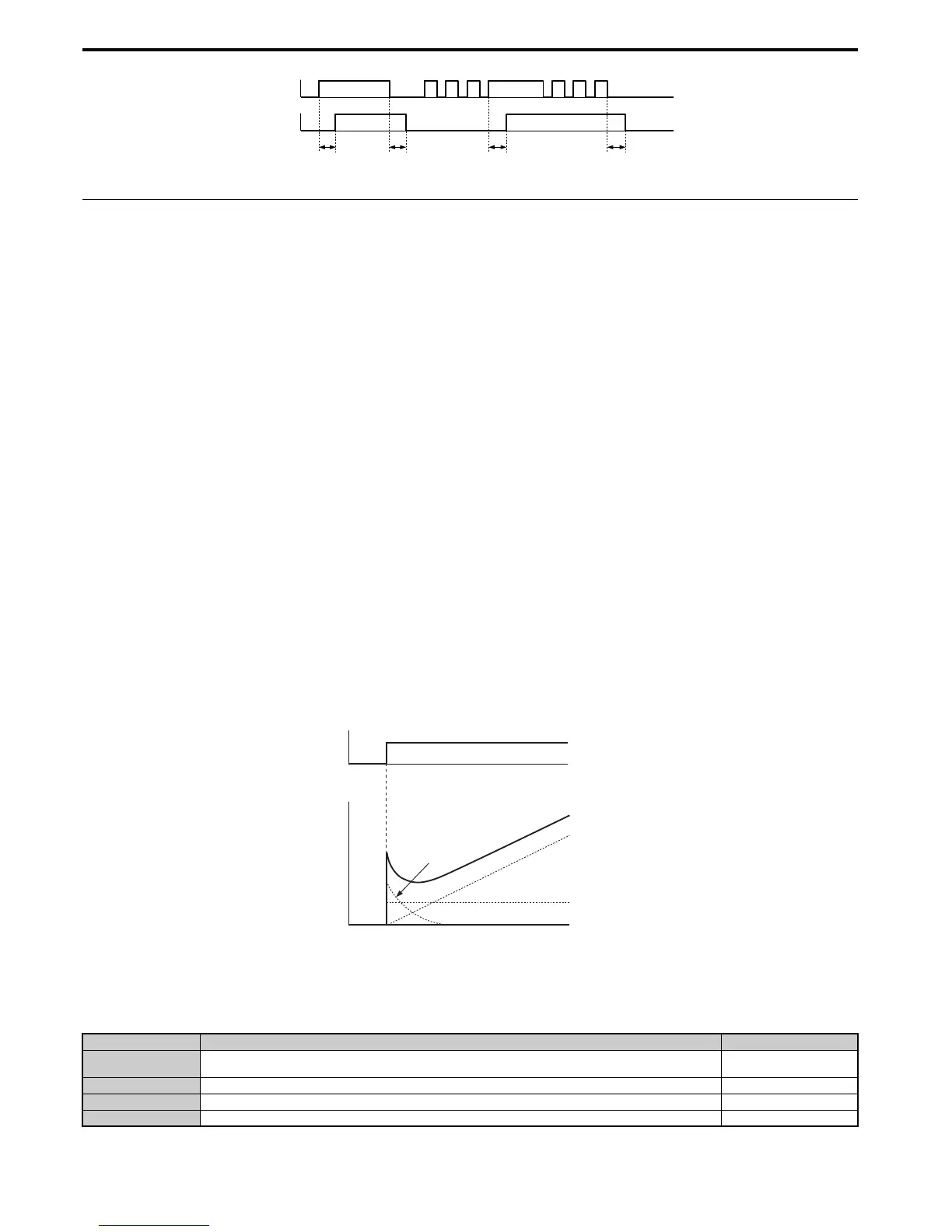
To better demonstrate how PID works, the diagram below shows how the PID output changes when the PID input
(deviation) jumps from 0 to a constant level.
Figure 5. 22
Figure 5.22 PID Operation
■ Using PID Control
Applications for PID control are listed in the table below.
Application Description Sensors Used
Speed Control
Machinery speed is fed back and adjusted to meet the target value. Synchronous control is performed using speed data from
other machinery as the target value
Tachometer
Pressure Maintains constant pressure using pressure feedback. Pressure sensor
Fluid Control Keeps flow at a constant level by feeding back flow data. Flow rate sensor
Temperature Control Maintains a constant temperature by controlling a fan with a thermostat. Thermocoupler, Thermistor

 Loading...


