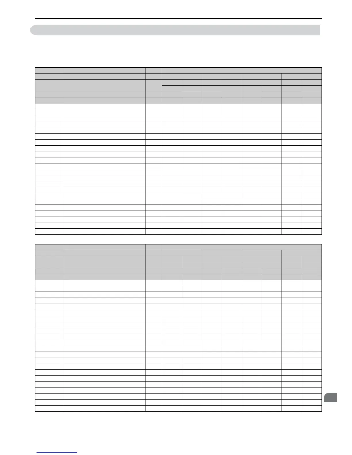
B.6 Defaults by Drive Model Selection (o2-04) and ND/HD (C6-01)
The following tables show parameters and default settings that change with the drive model selection (o2-04). Parameter
numbers shown in parenthesis are valid for motor 2.
Table B.8 200 V Class Drives Default Settings by Drive Model Selection and ND/HD settings
No. Name Unit Default Settings
Model CIMR-A – 2A0004 2A0006 2A0010 2A0012
C6-01 Drive Duty Selection –
HD ND HD ND HD ND HD ND
0 1 0 1 0 1 0 1
o2-04 Drive Model Selection Hex. 62 63 65 66
E2-11 (E4-11) Motor rated Output kW 0.4 0.75 0.75 1.1 1.5 2.2 2.2 3.0
b3-04 V/f Gain during Speed Search % 100 100 100 100 100 100 100 100
b3-06 Output Current 1 during Speed Search – 1 1 0.5 0.5 0.5 0.5 0.5 0.5
b8-03 Energy Saving Control Filter Time Constant s 0.50 0.50 0.50 0.50 0.50 0.50 0.50 0.50
b8-04 Energy Saving Coefficient Value – 288.2 223.7 223.7 196.6 169.4 156.8 156.8 136.4
C5-17 (C5-37) Motor Inertia
kgm
2
0.0015 0.0028 0.0028 0.0068 0.0068 0.0088 0.0088 0.0158
C6-02 Carrier Frequency Selection – 1 7 1 7 1 7 1 7
E2-01 (E4-01) Motor Rated Current A 1.9 3.3 3.3 4.9 6.2 8.5 8.5 11.4
E2-02 (E4-02) Motor Rated Slip Hz 2.9 2.5 2.5 2.6 2.6 2.9 2.9 2ÅD7
E2-03 (E4-03) Motor No-Load Current A 1.2 1.8 1.8 2.3 2.8 3 3 3.7
E2-05 (E4-05) Motor Line to Line Resistance Ω 9.842 5.156 5.156 3.577 1.997 1.601 1.601 1.034
E2-06 (E4-06) Motor Leakage Inductance % 18.2 13.8 13.8 18.5 18.5 18.4 18.4 19
E2-10 (E4-10) Motor Iron Loss for Torque Compensation W 14 26 26 38 53 77 77 91
E5-01 Motor Code Selection Hex. 1202 1202 1203 1203 1205 1205 1206 1206
L2-02 Momentary Power Loss Ride-Thru Time s 0.1 0.1 0.2 0.2 0.3 0.3 0.5 0.5
L2-03 Momentary Power Loss Minimum Baseblock Time s 0.2 0.3 0.3 0.4 0.4 0.5 0.5 0.5
L2-04 Momentary Power Loss Voltage Recovery Time s 0.3 0.3 0.3 0.3 0.3 0.3 0.3 0.3
L3-24 Motor Acceleration Time for Inertia Calculations s 0.178 0.142 0.142 0.142 0.166 0.145 0.145 0.145
L8-02 Overheat Alarm Level °C 115 115 115 115 115 115 125 125
L8-35 Installation Method Selection – 2 2 2 2 2 2 2 2
L8-38 Carrier Frequency Reduction Selection –22222222
n1-03 Hunting Prevention Time Constant ms 10 10 10 10 10 10 10 10
n5-02 Motor Acceleration Time s 0.178 0.142 0.142 0.142 0.166 0.145 0.145 0.145
No. Name Unit Default Settings
Model CIMR-A – 2A0021 2A0030 2A0040 2A0056
C6-01 Drive Duty Selection –
HD ND HD ND HD ND HD ND
0 1 0 1 0 1 0 1
o2-04 Drive Model Selection Hex. 68 6A 6B 6D
E2-11 (E4-11) Motor rated Output kW 3.7 5.5 5.5 7.5 7.5 11 11 15
b3-04 V/f Gain during Speed Search % 100 100 100 100 100 100 100 100
b3-06 Output Current 1 during Speed Search – 0.5 0.5 0.5 0.5 0.5 0.5 0.5 0.5
b8-03 Energy Saving Control Filter Time Constant s 0.50 0.50 0.50 0.50 0.50 0.50 0.50 0.50
b8-04 Energy Saving Coefficient Value – 122.9 94.75 94.75 72.69 72.69 70.44 70.44 63.13
C5-17 (C5-37) Motor Inertia
kgm
2
0.0158 0.0255 0.026 0.037 0.037 0.053 0.053 0.076
C6-02 Carrier Frequency Selection – 1 7 1 7 1 7 1 7
E2-01 (E4-01) Motor Rated Current A 14 19.6 19.6 26.6 26.6 39.7 39.7 53
E2-02 (E4-02) Motor Rated Slip Hz 2.73 1.5 1.5 1.3 1.3 1.7 1.7 1.6
E2-03 (E4-03) Motor No-Load Current A 4.5 5.1 5.1 8 8 11.2 11.2 15.2
E2-05 (E4-05) Motor Line to Line Resistance Ω 0.771 0.399 0.399 0.288 0.288 0.23 0.23 0.138
E2-06 (E4-06) Motor Leakage Inductance % 19.6 18.2 18.2 15.5 15.5 19.5 19.5 17.2
E2-10 (E4-10) Motor Iron Loss for Torque Compensation W 112 172 172 262 262 245 245 272
E5-01 Motor Code Selection Hex. 1208 1208 120A 120A 120B 120B 120D 120D
L2-02 Momentary Power Loss Ride-Thru Time s 1 1 1 1 1 1 2 2
L2-03 Momentary Power Loss Minimum Baseblock Time s 0.6 0.7 0.7 0.8 0.8 0.9 0.9 1
L2-04 Momentary Power Loss Voltage Recovery Time s 0.3 0.3 0.3 0.3 0.3 0.3 0.3 0.6
L3-24 Motor Acceleration Time for Inertia Calculations s 0.154 0.168 0.168 0.175 0.175 0.265 0.265 0.244
L8-02 Overheat Alarm Level °C 110 110 120 120 125 125 120 120
L8-35 Installation Method Selection – 2 2 2 2 2 2 2 2
L8-38 Carrier Frequency Reduction Selection –22222222
n1-03 Hunting Prevention Time Constant ms 10 10 10 10 10 10 10 10
n5-02 Motor Acceleration Time s 0.154 0.168 0.168 0.175 0.175 0.265 0.265 0.244

 Loading...


