EasyManuals Logo

YASKAWA A1000 Series Technical Manual

YASKAWA A1000 Series
544 pages
To Next Page IconTo Next Page
To Previous Page IconTo Previous Page
Page #447 background imageLoading...
Page #447 background image
B.3 Parameter Table
YASKAWA ELECTRIC SIEP C710616 27C YASKAWA AC Drive A1000 Technical Manual 447
Parameter List
B
U: Monitors
Monitor parameters allow the user to view drive status, fault information, and other data concerning drive operation.
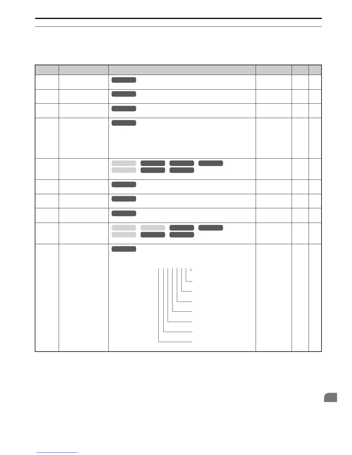
U1: Operation Status Monitors
No. (Addr.) Name Description
Analog Output
Level
Unit Page
U1-01
(40H)
Frequency Reference
Monitors the frequency reference. Display units are determined by o1-03.
10 V: Max frequency 0.01 Hz
U1-02
(41H)
Output Frequency
Displays the output frequency. Display units are determined by o1-03.
10 V: Max frequency 0.01 Hz
U1-03
(42H)
Output Current
Displays the output current.
10 V: Drive rated
current
<19> <50>
U1-04
(43H)
Control Method
0: V/f Control
1: V/f Control with PG
2: Open Loop Vector Control
3: Closed Loop Vector Control
5: Open Loop Vector Control for PM
6: Advanced Open Loop Vector Control for PM
7: Closed Loop Vector Control for PM
No signal output
available
––
U1-05
(44H)
Motor Speed
Displays the motor speed feedback. Display units are determined by o1-03.
10 V: Max Frequency 0.01 Hz
U1-06
(45H)
Output Voltage Reference
Displays the output voltage.
10 V: 200 Vrms
<18> 0.1 Vac
U1-07
(46H)
DC Bus Voltage
Displays the DC bus voltage.
10 V: 400 V
<18> 1 Vdc
U1-08
(47H)
Output Power
Displays the output power (this value is calculated internally).
10 V: Drive rated
power (kW)
<22>
U1-09
(48H)
Torque Reference
Monitors the internal torque reference.
10 V: Motor rated
torque
0.1%
U1-10
(49H)
Input Terminal Status
Displays the input terminal status.
No signal output
available
––
All Modes
common_
TMonly
All Modes
common_
TMonly
All Modes
common_
TMonly
All Modes
common_
TMonly
OLV/PM AOLV/PM
CLV
V/f w/PG
CLV/PM
V/f OLV
common_
TMonly
All Modes
common_
TMonly
All Modes
common_
TMonly
All Modes
common_
TMonly
OLV/PM AOLV/PM
CLV
V/f w/PG
CLV/PM
V/f OLV
common_
TMonly
All Modes
common_
TMonly
U1
-
10=
00000000
Digital input 1
(terminal S1 enabled)
Digital input 2
(terminal S2 enabled)
Digital input 3
(terminal S3 enabled)
Digital input 4
(terminal S4 enabled)
Digital input 5
(terminal S5 enabled)
Digital input 6
(terminal S6 enabled)
Digital input 7
(terminal S7 enabled)
Digital input 8
(terminal S8 enabled)
1
1
1
1
1
1
1
1
YEG

Table of Contents

Other manuals for YASKAWA A1000 Series

Questions and Answers:

Question and Answer IconNeed help?

Do you have a question about the YASKAWA A1000 Series and is the answer not in the manual?

YASKAWA A1000 Series Specifications

General IconGeneral
SeriesA1000
TypeAC Drive
AltitudeUp to 1000m without derating
Output Frequency0-400 Hz
Control MethodV/f Control
Overload Capacity150% for 60 seconds
Communication OptionsModbus, DeviceNet, Profibus, Ethernet/IP
Ambient Temperature-10 to 50°C
Storage Temperature-20 to 60°C
Humidity5% to 95% (non-condensing)
Enclosure RatingIP20
Horsepower0.5 to 1000 HP
Power Range0.4 - 630 kW (varies by voltage and model)
Protection FeaturesOvercurrent, Overvoltage, Undervoltage, Overheat
Cooling MethodFan Cooled
SafetySafe Torque Off (STO)

Related product manuals