B.3 Parameter Table
448 YASKAWA ELECTRIC SIEP C710616 27C YASKAWA AC Drive A1000 Technical Manual
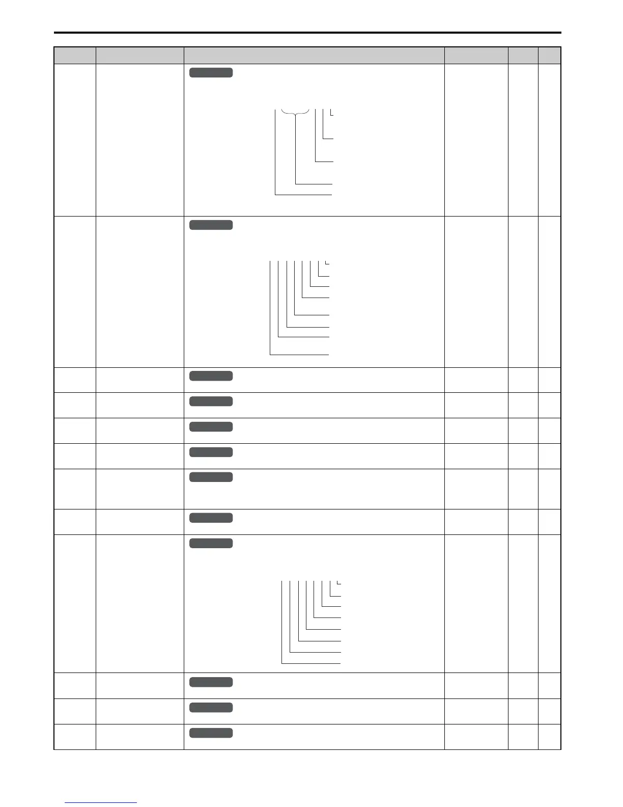
U1-11
(4AH)
Output Terminal Status
Displays the output terminal status.
No signal output
available
––
U1-12
(4BH)
Drive Status
Verifies the drive operation status.
No signal output
available
––
U1-13
(4EH)
Terminal A1 Input Level
Displays the signal level to analog input terminal A1.
10 V: 100% 0.1% –
U1-14
(4FH)
Terminal A2 Input Level
Displays the signal level to analog input terminal A2.
10 V: 100% 0.1% –
U1-15
(50H)
Terminal A3 Input Level
Displays the signal level to analog input terminal A3.
10 V: 100% 0.1% –
U1-16
(53H)
Output Frequency after Soft
Starter
Displays output frequency with ramp time and S-curves. Units determined by o1-03.
10 V: Max frequency 0.01 Hz –
U1-17
(58H)
DI-A3 Input Status
Displays the reference value input from the DI-A3 option card.
Display will appear in hexadecimal as determined by the digital card input selection in F3-01.
3FFFF: Set (1 bit) + sign (1 bit) + 16 bit
No signal output
available
––
U1-18
(61H)
oPE Fault Parameter
Displays the parameter number that caused the oPE or Err (EEPROM write error) error.
No signal output
available
––
U1-19
(66H)
MEMOBUS/Modbus Error
Code
Displays the contents of a MEMOBUS/Modbus error.
No signal output
available
––
U1-21
(77H)
AI-A3 Terminal V1 Input
Voltage Monitor
Displays the input voltage to terminal V1 on analog input card AI-A3.
10 V: 100% 0.1% –
U1-22
(72AH)
AI-A3 Terminal V2 Input
Voltage Monitor
Displays the input voltage to terminal V2 on analog input card AI-A3.
10 V: 100% 0.1% –
U1-23
(72BH)
AI-A3 Terminal V3 Input
Voltage Monitor
Displays the input voltage to terminal V3 on analog input card AI-A3.
10 V: 100% 0.1% –
No. (Addr.) Name Description
Analog Output
Level
Unit Page

 Loading...


