B.3 Parameter Table
442 YASKAWA ELECTRIC SIEP C710616 27C YASKAWA AC Drive A1000 Technical Manual
◆ o: Operator Related Settings
The o parameters are used to set up the digital operator displays.
■
o1: Digital Operator Display Selection
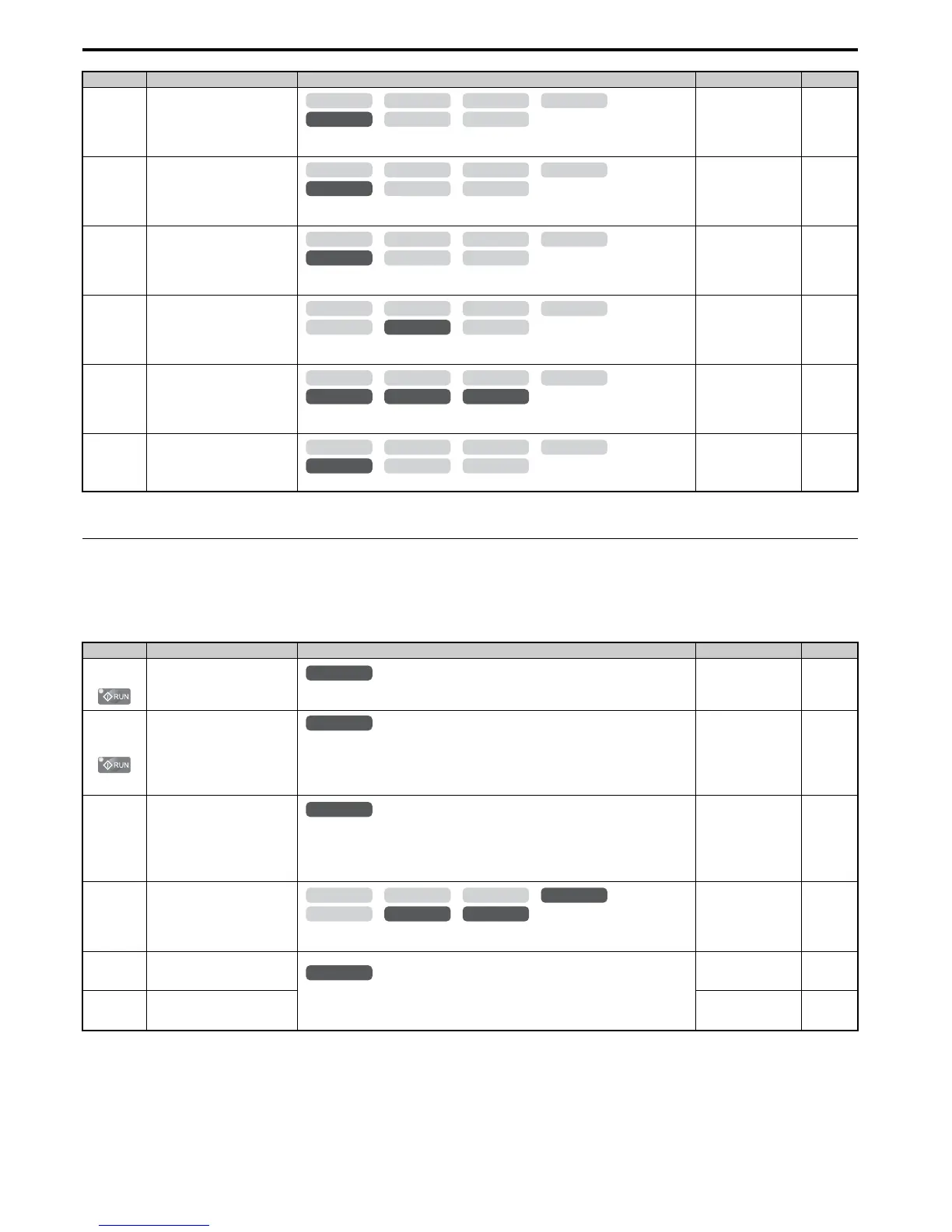
n8-51
(53EH)
Acceleration/Deceleration Pull-In
Current
Sets the d-axis current reference during acceleration/deceleration as a percentage of the motor
rated current. Set to a high value when more starting torque is needed.
Default: 50%
Min: 0%
Max: 200%
282
n8-54
(56DH)
Voltage Error Compensation Time
Constant
Adjusts the value when hunting occurs at low speed. If hunting occurs with sudden load
changes, increase n8-54 in increments of 0.1. Reduce this setting if oscillation occurs at start.
Default: 1.00 s
Min: 0.00 s
Max: 10.00 s
282
n8-55
(56EH)
Load Inertia
For large inertia loads or to increase the speed control response, increase this setting. Too high
of a setting when driving a very light load or load with very low inertia can result in oscillation.
Default: 0
Min: 0
Max: 3
283
n8-57
(574H)
High Frequency Injection
0: Disabled. Disable when using an SPM motor.
1: Enabled. Use this setting to enhance the speed control range when using an IPM motor.
Default: 0
Min: 0
Max: 1
283
n8-62
(57DH)
<18>
Output Voltage Limit
Prevents output voltage saturation. Should be set just below the voltage provided by the input
power supply.
Default: 200.0 V
Min: 0.0 V
Max: 230.0 V
283
n8-65
(65CH)
Speed Feedback Detection Control
Gain during ov Suppression
Sets the gain used for internal speed feedback detection during ov suppression
Default: 1.50
Min: 0.00
Max: 10.00
283
<14> Default setting value is dependent on the motor code set to E5-01.
<18> Values shown here are for 200 V class drives. Double the value when using a 400 V class drive.
No. (Addr.) Name Description Setting Page
o1-01
(500H)
<10> Default setting is determined by the control mode (A1-02).
<36> Default setting value is determined by the digital operator display selection (o1-03).
Drive Mode Unit Monitor
Selection Selects the content of the last monitor that is shown when scrolling through Drive Mode
display. Enter the last three digits of the monitor parameter number to be displayed: U-.
Default: 106 (Monitor
U1-06)
Min: 104
Max: 809
284
o1-02
(501H)
User Monitor Selection after
Power Up
1: Frequency reference (U1-01)
2: Direction
3: Output frequency (U1-02)
4: Output current (U1-03)
5: User-selected monitor (set by o1-01)
Default: 1
Min: 1
Max: 5
284
o1-03
(502H)
Digital Operator Display Selection
Sets the units the drive should use to display the frequency reference and motor speed monitors.
0: 0.01 Hz
1: 0.01% (100% = E1-04)
2: r/min (calculated using the number of motor poles setting in E2-04, E4-04, or E5-04)
3: User-selected units (set by o1-10 and o1-11)
Default:
<10>
Min: 0
Max: 3
284
o1-04
(503H)
V/f Pattern Display Unit
0: Hz
1: r/min
Default: <10>
Min: 0
Max: 1
285
o1-10
(520H)
User-Set Display Units Maximum
Va lu e
These settings define the display values when o1-03 is set to 3.
o1-10 sets the display value that is equal to the maximum output frequency.
o1-11 sets the position of the decimal position.
Default:
<36>
Min: 1
Max: 60000
285
o1-11
(521H)
User-Set Display Units Decimal
Display
Default:
<36>
Min: 0
Max: 3
285
No. (Addr.) Name Description Setting Page
OLV/PM AOLV/PM
CLV
V/f w/PG
CLV/PM
V/f OLV

 Loading...


