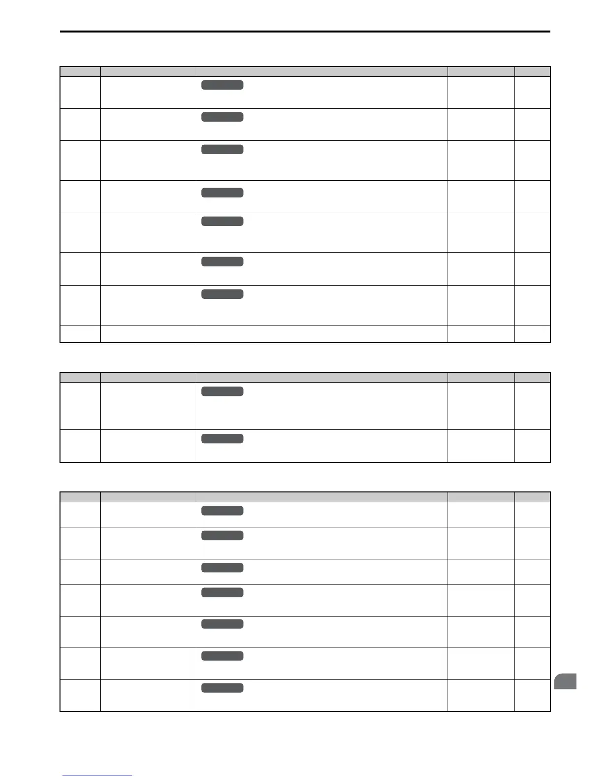
■ o2: Digital Operator Keypad Functions
■ o3: Copy Function
■ o4: Maintenance Monitor Settings
No. (Addr.) Name Description Setting Page
o2-01
(505H)
LO/RE Key Function Selection
0: Disabled
1: Enabled. LO/RE key switches between LOCAL and REMOTE operation.
Default: 1
Min: 0
Max: 1
285
o2-02
(506H)
STOP Key Function Selection
0: Disabled. STOP key is disabled in REMOTE operation.
1: Enabled. STOP key is always enabled.
Default: 1
Min: 0
Max: 1
286
o2-03
(507H)
User Parameter Default Value 0: No change.
1: Set defaults. Saves parameter settings as default values for a User Initialization.
2: Clear all. Clears the default settings that have been saved for a User Initialization.
Default: 0
Min: 0
Max: 2
286
o2-04
(508H)
Drive Model Selection
Enter the drive model. Setting required only if installing a new control board.
Default: Determined by
drive capacity
Min: –
Max: –
286
o2-05
(509H)
Frequency Reference Setting
Method Selection
0: ENTER key must be pressed to enter a frequency reference.
1: ENTER key is not required. The frequency reference can be adjusted using the up and down
arrow keys only.
Default: 0
Min: 0
Max: 1
286
o2-06
(50AH)
Operation Selection when Digital
Operator is Disconnected
0: The drive continues operating if the digital operator is disconnected.
1: A fault is triggered (oPr) and the motor coasts to stop.
Default: 0
Min: 0
Max: 1
287
o2-07
(527H)
Motor Direction at Power Up when
Using Operator
0: Forward
1: Reverse
This parameter requires that drive operation be assigned to the digital operator.
Default: 0
Min: 0
Max: 1
287
o2-09
(50DH)
Reserved – ––
No. (Addr.) Name Description Setting Page
o3-01
(515H)
Copy Function Selection
0: No action
1: Read parameters from the drive, saving them onto the digital operator.
2: Copy parameters from the digital operator, writing them to the drive.
3: Verify parameter settings on the drive to check if they match the data saved on the operator.
Default: 0
Min: 0
Max: 3
287
o3-02
(516H)
Copy Allowed Selection
0: Read operation prohibited
1: Read operation allowed
Default: 0
Min: 0
Max: 1
287
No. (Addr.) Name Description Setting Page
o4-01
(50BH)
Cumulative Operation Time
Setting
Sets the value for the cumulative operation time of the drive in units of 10 h.
Default: 0 h
Min: 0 h
Max: 9999 h
288
o4-02
(50CH)
Cumulative Operation Time
Selection
0: Logs power-on time
1: Logs operation time when the drive output is active (output operation time).
Default: 0
Min: 0
Max: 1
288
o4-03
(50EH)
Cooling Fan Operation Time
Setting
Sets the value of the fan operation time monitor U4-03 in units of 10 h.
Default: 0 h
Min: 0 h
Max: 9999 h
288
o4-05
(51DH)
Capacitor Maintenance Setting
Sets the value of the Maintenance Monitor for the capacitors. See U4-05 to check when the
capacitors may need to be replaced.
Default: 0%
Min: 0%
Max: 150%
288
o4-07
(523H)
DC Bus Pre-Charge Relay
Maintenance Setting
Sets the value of the Maintenance Monitor for the soft charge bypass relay. See U4-06 to check
when the bypass relay may need to be replaced.
Default: 0%
Min: 0%
Max: 150%
288
o4-09
(525H)
IGBT Maintenance Setting
Sets the value of the Maintenance Monitor for the IGBTs. See U4-07 to check when the IGBTs
may need to be replaced.
Default: 0%
Min: 0%
Max: 150%
289
o4-11
(510H)
U2, U3 Initialization
0: U2- and U3- monitor data is not reset when the drive is initialized (A1-03).
1: U2- and U3- monitor data is reset when the drive is initialized (A1-03).
Default: 0
Min: 0
Max: 1
289
All Modes

 Loading...


