Table 5.38 Multi-Function Digital Output Terminal Settings
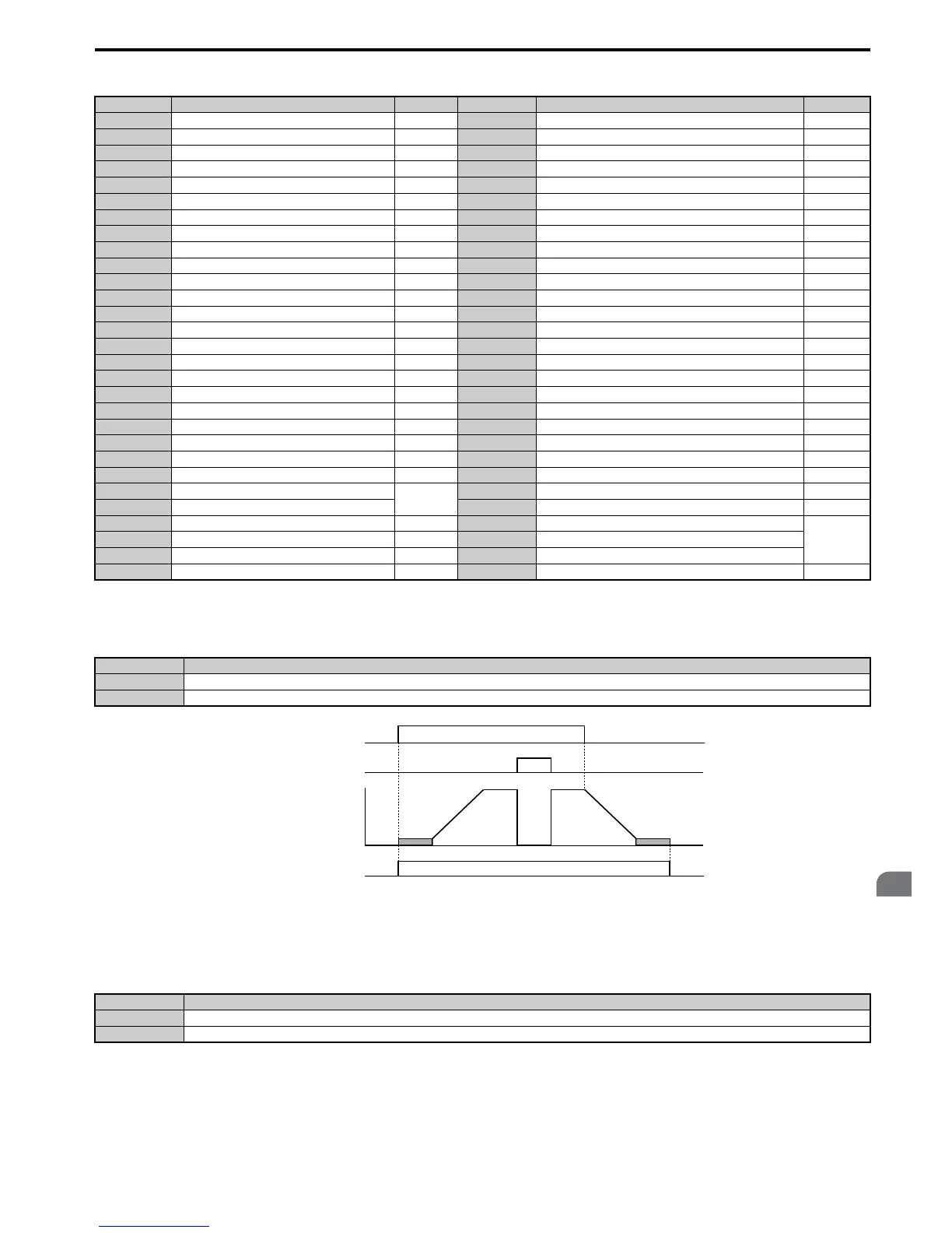
Setting 0: During Run
Output closes when the drive is outputting a voltage.
Figure 5.65
Figure 5.65 During Run Time Chart
Setting 1: Zero Speed
Terminal closes whenever the output frequency or motor speed (CLV, CLV/PM) falls below the minimum output
frequency set to E1-09 or b2-01.
Note: When using CLV or CLV/PM control modes, the zero speed level is defined by b2-01. In all other control modes, the zero speed
level is the minimum output frequency set to E1-09.
Setting Function Page Setting Function Page
0 During run 225 1D During regeneration 231
1 Zero Speed 225 1E Restart enabled 231
2 Speed agree 1 226 1F Motor overload alarm (oL1) 231
3 User-set speed agree 1 226 20 Drive overheat pre-alarm (oH) 231
4 Frequency detection 1 227 22 Mechanical Weakening detection 231
5 Frequency detection 2 227 2F Maintenance period 232
6 Drive ready 227 30 During torque limit 232
7 DC bus undervoltage 228 31 During speed limit 232
8 During baseblock (N.O.) 228 32 During speed limit in Torque Control 232
9 Frequency reference source 228 33 Zero Servo complete 232
A Run command source 228 37 During frequency output 232
B Torque detection 1 (N.O.) 228 38 Drive enabled 232
C Frequency reference loss 228 39 Watt hour pulse output 232
D Braking resistor fault 228 3C LOCAL/REMOTE Status 233
EFault 228 3D During Speed Search 233
F Through mode 229 3E PID feedback low 233
10 Minor fault 229 3F PID feedback high 233
11 Fault reset command active 229 4A During KEB operation 233
12 Timer output 229 4B During Short Circuit Braking 233
13 Speed agree 2 229 4C During Fast Stop 233
14 User-set speed agree 2 229 4D oH pre-alarm time limit 233
15 Frequency detection 3 230 4E Braking transistor fault (rr) 233
16 Frequency detection 4 230 4F Braking resistor overheat (rH) 233
17 Torque detection 1 (N.C.)
228
60 Internal cooling fan alarm 233
18 Torque detection 2 (N.O.) 61 Rotor Position Detection Completed 233
19 Torque detection 2 (N.C.) 228 90 DriveWorksEZ digital output 1
233
1A During reverse 231 91 DriveWorksEZ digital output 2
1B During baseblock (N.C.) 231 92 DriveWorksEZ digital output 3
1C Motor 2 selection 231 100 to 192 Functions 0 to 92 with inverse output 233
Status Description
Open Drive is stopped.
Closed A Run command is input or the drive is during deceleration or during DC injection.
Status Description
Open Output frequency is above the minimum output frequency set to E1-09 or b2-01
Closed Output frequency is less than the minimum output frequency set to E1-09 or b2-01

 Loading...


