■ b2-02: DC Injection Braking Current
Sets the DC Injection Braking current as a percentage of the drive rated current. If set larger than 50%, the carrier
frequency is automatically reduced to 1 kHz.
The level of DC Injection Braking current affects the strength of the magnetic field attempting to lock the motor shaft.
Increasing the current level will increase the amount of heat generated by the motor windings. This parameter should
only be increased to the level necessary to hold the motor shaft.
■
b2-03: DC Injection Braking Time at Start
Sets the time of DC Injection Braking (Zero Speed Control when in CLV and CLV/PM) at start. Used to stop a coasting
motor before restarting it or to apply braking torque at start. Disabled when set to 0.00 s.
Note: Before starting an uncontrolled rotating motor (e.g., a fan motor driven by windmill effect), DC Injection or Speed Search should
be used to either stop the motor or detect its speed before starting it. Otherwise motor stalling and other faults can occur.
■ b2-04: DC Injection Braking Time at Stop
Sets the time of DC Injection Braking (Zero Speed Control when in CLV and CLV/PM) at stop. Used to completely stop
a motor with high inertia load after ramp down. Increase the value if the motor still coasts by inertia after it should have
stopped. Disabled when set to 0.00 s.
■
b2-08: Magnetic Flux Compensation Value
Sets the magnetic flux compensation at start as a percentage of the no-load current value (E2-03). This function allows
better more flux to develop, making it easier to start machines that require high starting torque or motors with a large
rotor time constant.
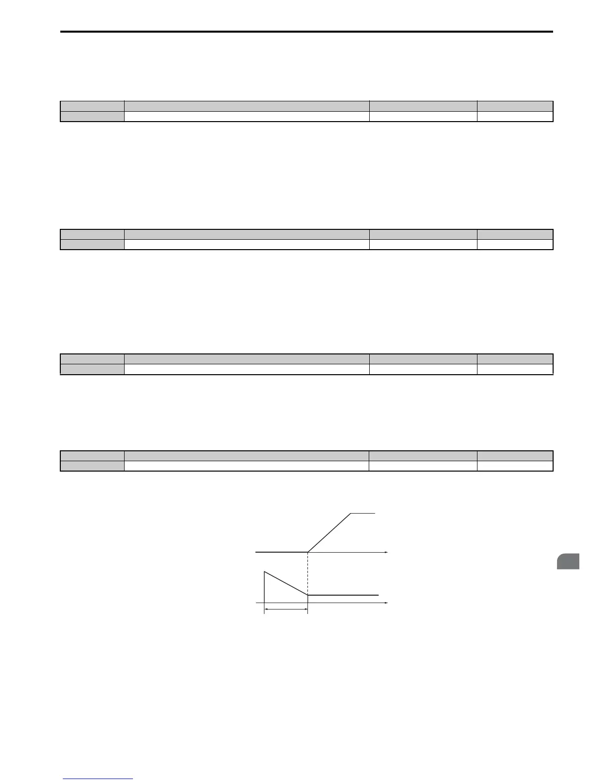
When a Run command is issued, the DC current level injected into the motor changes linearly from the level set to b2-08
to E2-03 within the time set to b2-03.
Figure 5.16
Figure 5.16 Magnetic Flux Compensation
Note that the level of the DC current injected to the motor is limited to 80% of the drive rated current or to the motor
rated current, whichever value is smaller.
Note: 1. If b2-08 is set below 100%, it can take a relatively long time for flux to develop.
2. If b2-08 is set to 0%, the DC current level will be the DC Injection current set to b2-02.
3. As DC Injection can generate a fair amount of noise, b2-08 may need to be adjusted to keep noise levels acceptable.
No. Name Setting Range Default
b2-02 DC Injection Braking Current 0 to 100% 50%
No. Name Setting Range Default
b2-03 DC Injection Braking Time at Start 0.00 to 10.00 s 0.00 s
No. Name Setting Range Default
b2-04 DC Injection Braking Time at Stop 0.00 to 10.00 s Determined by A1-02
No. Name Setting Range Default
b2-08 Magnetic Flux Compensation Value 0 to 1000% 0%
E2-03
Time
b2-03
Magnetizing Current
Reference
b2-08
Output frequency

 Loading...


