■ b5-01: PID Function Setting
Enables or disables the PID operation and selects the PID operation mode.
Setting 0: PID disabled
Setting 1: Output frequency = PID output 1
The PID controller is enabled and the PID output builds the frequency reference. The PID input is D controlled.
Setting 2: Output frequency = PID output 2
The PID controller is enabled and the PID output builds the frequency reference. The PID feedback is D controlled.
Setting 3: Output frequency = frequency reference + PID output 1
The PID controller is enabled and the PID output is added to the frequency reference. The PID input is D controlled.
Setting 4: Output frequency = frequency reference + PID output 2
The PID controller is enabled and the PID output is added to the frequency reference. The PID feedback is D controlled.
■
b5-02: Proportional Gain Setting (P)
Sets the P gain that is applied to the PID input. A large value will tend to reduce the error, but may cause instability
(oscillations) if set too high. A low value may allow too much offset between the setpoint and feedback.
■
b5-03: Integral Time Setting (I)
Sets the time constant that is used to calculate the integral of the PID input. The smaller the integral time set to b5-03, the
faster the offset will be eliminated. If set too short, it can cause overshoot or oscillation. To turn off the integral time, set
b5-03 = 0.00.
■
b5-04: Integral Limit Setting
Sets the maximum output possible from the integral block. Set as a percentage of the maximum frequency (E1-04).
Note: On some applications, especially those with rapidly varying loads, the output of the PID function may show a fair amount of
oscillation. To suppress this oscillation, a limit can be applied to the integral output by programming b5-04.
■ b5-05: Derivative Time (D)
Sets the time the drive predicts the PID input/PID feedback signal based on the derivative of the PID input/PID feedback.
Longer time settings will improve the response but can cause vibrations. Shorter settings will reduce the overshoot but
also reduce the controller responsiveness. D control is disabled by setting b5-05 to zero seconds.
■
b5-06: PID Output Limit
Sets the maximum output possible from the entire PID controller. Set as a percentage of the maximum frequency (E1-
04).
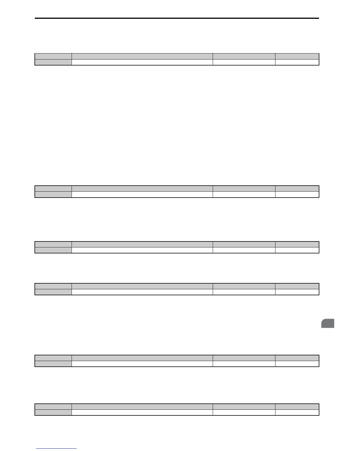
No. Parameter Name Setting Range Default
b5-01 PID Function Setting 0 to 4 0
No. Name Setting Range Default
b5-02 Proportional Gain Setting (P) 0.00 to 25.00 1.00
No. Name Setting Range Default
b5-03 Integral Time Setting (I) 0.0 to 360.0 s 1.0 s
No. Name Setting Range Default
b5-04 Integral Limit Setting 0.0 to 100.0% 100.0%
No. Name Setting Range Default
b5-05 Derivative Time (D) 0.00 to 10.00 s 0.00 s
No. Name Setting Range Default
b5-06 PID Output Limit 0.0 to 100.0% 100.0%

 Loading...


