5.5 E: Motor Parameters
200 YASKAWA ELECTRIC SIEP C710616 27C YASKAWA AC Drive A1000 Technical Manual
■ E2-09: Motor Mechanical Loss
This parameter sets to the motor mechanical loss as a percentage of motor rated power (kW) capacity.
Adjust this setting in the following circumstances:
• When there is a large amount of torque loss due to motor bearing friction.
• When there is a large amount of torque loss in a fan or pump application.
The setting for the mechanical loss is added to the torque.
■
E2-10: Motor Iron Loss for Torque Compensation
This parameter sets the motor iron loss in watts.
■
E2-11: Motor Rated Power
This parameter sets the motor rated power in kW. If Auto-Tuning completes successfully, the value entered to T1-02 will
automatically be saved to E2-11.
■
Setting Motor Parameters Manually
Follow the instructions below when setting motor-related parameters manually instead of using the Auto-Tuning feature.
Refer to the motor test report included with the motor to make sure the correct data is entered into the drive.
Setting the Motor Rated Current
Enter the motor rated current listed on the nameplate of the motor to E2-01.
Setting the Motor Rated Slip
Use the base speed listed on the motor nameplate to calculate the rated slip. Refer to the formula below, then enter that
value to E2-02.
Motor rated slip = rated frequency [Hz] –base speed [r/min] × (no. of motor poles) / 120
Setting the No-Load Current
Enter the no-load current at rated frequency and rated voltage to E2-03. The no-load current is not usually listed on the
nameplate. Contact the motor manufacturer if the data cannot be found.
The default setting of the no-load current is for performance with a 4-pole Yaskawa motor.
Setting the Number of Motor Poles
Only required in V/f Control with PG and Closed Loop Vector Control. Enter the number of motor poles as indicated on
motor nameplate.
Setting the Line-to-Line Resistance
E2-05 is normally set during Auto-Tuning. If Auto-Tuning cannot be performed, contact the manufacturer of the motor to
find out what the correct resistance is between motor lines. The motor test report can also be used to calculate this value:
• E-type insulation: Multiply 0.92 times the resistance value (
Ω) listed on the test report at 75°C.
• B-type insulation: Multiply 0.92 times the resistance value (
Ω) listed on the test report at 75°C.
• F-type insulation: Multiply 0.87 times the resistance value (
Ω) listed on the test report at 115°C.
Setting the Motor Leakage Inductance
The motor leakage inductance set to E2-06 determines the amount of voltage drop relative to the motor rated voltage.
This value should be entered particularly for motors with a low degree of inductance, such as high-speed motors. As this
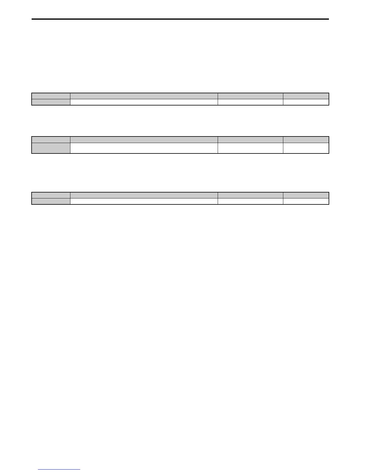
No. Parameter Name Setting Range Default
E2-09 Motor Mechanical Loss 0.0 to 10.0% 0.0%
No. Parameter Name Setting Range Default
E2-10 Motor Iron Loss for Torque Compensation 0 to 65535 W
Determined by C6-01 and
o2-04
No. Parameter Name Setting Range Default
E2-11 Motor Rated Power 0.00 to 650.00 kW Determined by o2-04

 Loading...


