■ KEB Operation Wiring Example
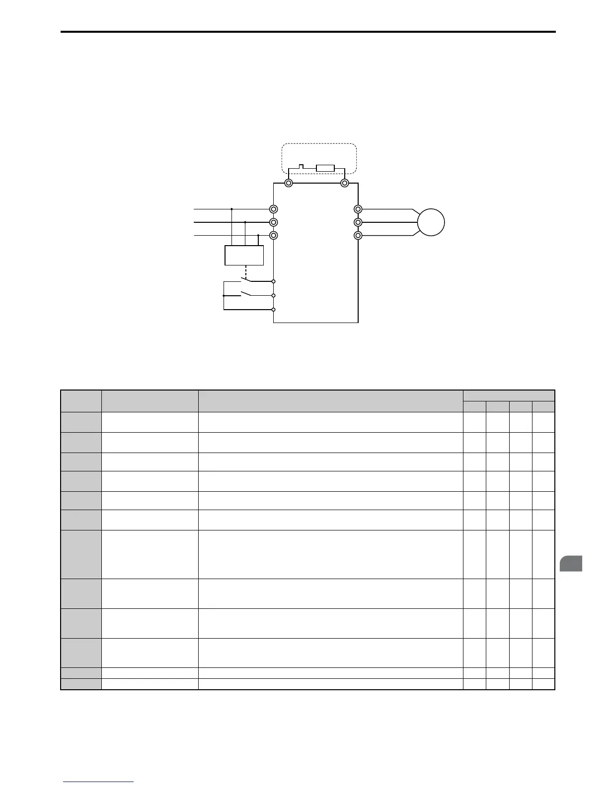
Figure 5.95 shows a wiring example for triggering the KEB Ride-Thru at power loss using an undervoltage relay. If
power loss occurs, the undervoltage relay triggers KEB Ride-Thru at terminal S6 (H1-06 = 65, 66, 7A, 7B). Note that an
additional dynamic braking option is required if System KEB Ride-Thru 1 is used.
Note: 1. Make sure the Run command is not switched off during momentary power loss. If the Run command is shut off, the drive will not
accelerate back to speed when the power is restored.
2. A dynamic braking option is required in order to use System KEB 1 (L2-29 = 2).
Figure 5.95
Figure 5.95 KEB Function Wiring Example
■ Parameters for KEB Ride-Thru
Table 5.4 0 lists parameters needed to set up KEB Ride-Thru depending the type of KEB Ride-Thru selected in L2-29.
Table 5.40 KEB Function Related Adjustments
Parameter Name Setting Instructions
KEB Mode (L2-29)
0 1 2 3
C1-09 Fast Stop Time
• Increase if an overvoltage fault (ov) occur during KEB deceleration.
• Decrease if an undervoltage fault (Uv1) occurs during KEB deceleration.
YESNONONO
C2-03 S-Curve at Deceleration Start
• Shorten if undervoltage (Uv1) occurs right after KEB Ride-Thru is triggered.
• Lengthen this setting if overvoltage occurs right after KEB operation starts.
YES NO YES YES
L2-05 Undervoltage Detection Level
Increase if an undervoltage fault (Uv1) fault occurs at KEB operation start in order to
let the drive detect power loss more quickly.
YESYESYESYES
L2-06 KEB Deceleration Time
• Increase if an overvoltage fault (ov) occur during KEB deceleration
• Decrease if an undervoltage fault (Uv1) occurs during KEB deceleration
NO NO YES YES
L2-07 KEB Acceleration Time
Adjust to the desired acceleration time. If set to 0, standard acceleration times are used
(C1-01, C1-03, C1-05, C1-07).
YESYESYESYES
L2-08 Frequency Gain at KEB Start
• Increase if an undervoltage fault occurs right after KEB operation starts.
• Decrease if an overvoltage fault occurs right after KEB operation starts.
YES NO YES YES
L2-10 KEB Detection Time
• Increase when a digital input is set for KEB Ride-Thru and an undervoltage fault
occurs after power was lost because the device that controls the input does not react
quickly enough.
• If the DC bus voltage overshoots after KEB Ride-Thru begins (and no input terminal
is set to KEB Ride-Thru), increase L2-10 to longer than the overshoot.
YESYESYESYES
L2-11
Desired DC Bus Voltage
during KEB
• Set to around 1.22 times the input voltage for Single Drive KEB Ride-Thru 2.
• Set to around 1.4 times the input voltage for Single Drive KEB Ride-Thru 1 and
System KEB Ride-Thru modes.
YESYESYESYES
L3-20 Main Circuit Adjustment Gain
• Increase this setting slowly in steps of 0.1 if overvoltage (ov) or undervoltage (Uv1)
occurs at the beginning of deceleration
• Reduce if torque ripple occurs during deceleration while executing KEB Ride-Thru.
NO YES NO NO
L3-21
Accel/Decel Rate
Calculation Gain
• Reduce L3-21 in steps of 0.05 if there is a fairly large speed or current ripple.
• Decreasing this setting too much can result in a slow DC bus voltage control
response, and may lead to problems with overvoltage or undervoltage.
NO YES NO NO
L3-24 Motor Acceleration Time Set the motor acceleration time as described on page 261. NO YES NO NO
L3-25 Load Inertia Ratio Set the load/inertia ratio as described on page 261. NO YES NO NO

 Loading...


