5.8 L: Protection Functions
268 YASKAWA ELECTRIC SIEP C710616 27C YASKAWA AC Drive A1000 Technical Manual
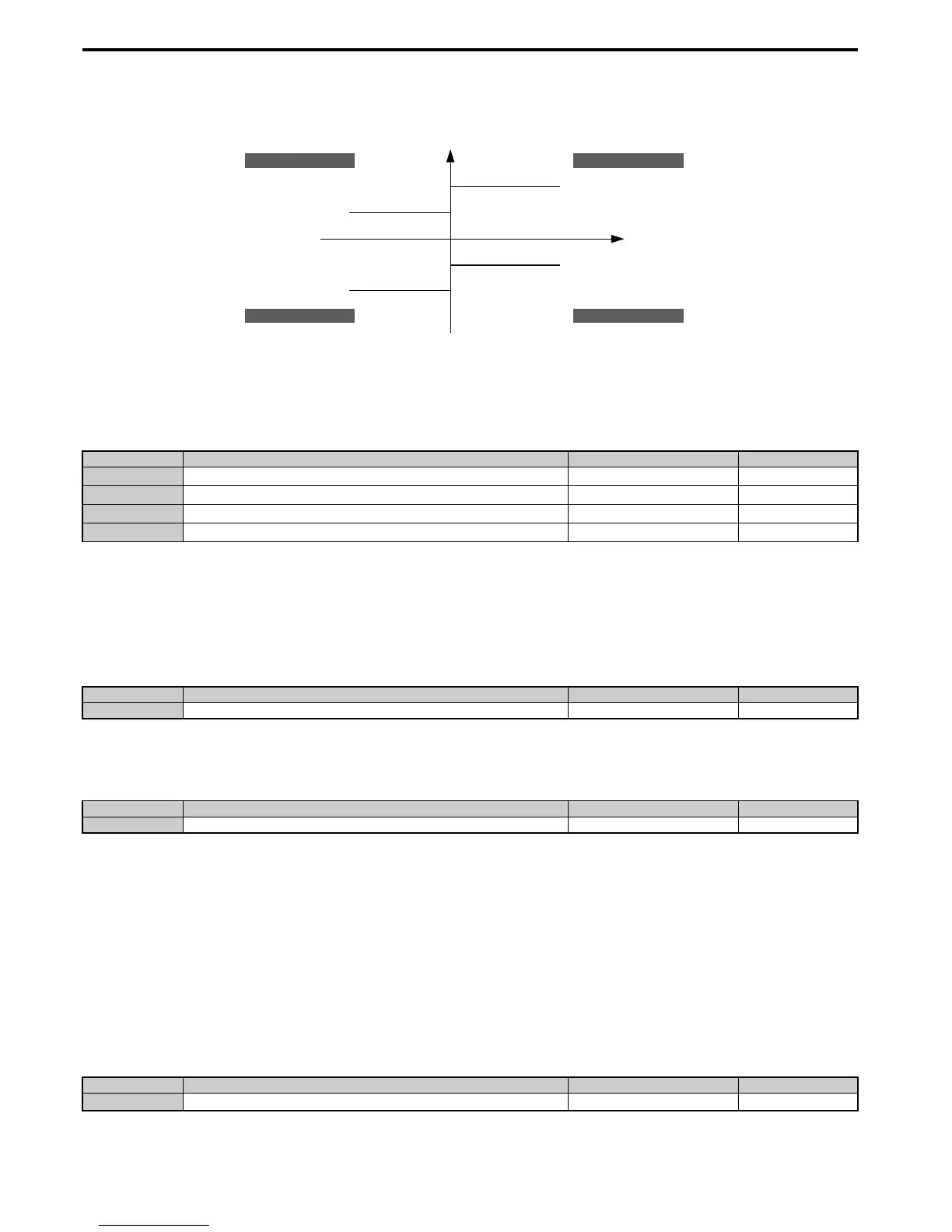
Example: If parameter L7-01 = 130%, L7-02 to L7-04 = 200%, and a general torque limit of 150% is set by an analog
input (H2-02, H2-06, H2-10 = 15), then the torque limit in quadrant 1 will be 130%, but 150% in all other quadrants.
Figure 5.10 3
Figure 5.103 Torque Limit Parameters and Analog Input Settings
■ L7-01 to L7-04: Torque Limits
These parameters set the torque limits in each operation mode.
Note: If the multi-function analog input is programmed for “10: Forward torque limit”, “11: Reverse torque limit”, “12: Regenerative
torque limit”, or “15: General torque limit”, the drive uses the lower value in L7-01 through L7-04, or analog input torque limit.
■ L7-06: Torque Limit Integral Time Constant
Sets the integral time constant for the torque limit function. Decrease this setting for faster torque limit response. Increase
it if oscillation occur when operating at the torque limit.
■
L7-07: Torque Limit Control Method Selection during Accel/Decel
Selects the function of torque limit during acceleration and deceleration.
Setting 0: Proportional control
The torque limit function works with P control during accel and decel, and switches to I control at constant speed. Use
this setting when accelerating or decelerating to the desired speed has priority over the torque limit during speed changes.
Setting 1: Integral control
The torque limit function always uses I control. Use this setting when a highly accurate torque limit is required, even
during speed changes. Using this function may increase the acceleration time, or may prevent the motor speed from
reaching the frequency reference if the torque limit is reached first.
■
L7-16: Torque Limit Process at Start
Assigns a time filter to allow the torque limit to build at start.
No. Name Setting Range Default
L7-01
Forward Torque Limit
0 to 300% 200%
L7-02
Reverse Torque Limit
0 to 300% 200%
L7-03
Forward Regenerative Torque Limit
0 to 300% 200%
L7-04
Reverse Regenerative Torque Limit
0 to 300% 200%
No. Name Setting Range Default
L7-06 Torque Limit Integral Time Constant 5 to 10000 ms 200 ms
No. Name Setting Range Default
L7-07 Torque Limit Control Method Selection during Accel/Decel 0 or 1 0
No. Name Setting Range Default
L7-16
Torque Limit Process at Start
0 to 1 1
positive torque reference
negative torque reference
10: Positive Torque Limit
12: Regenerative Torque Limit
15: Torque Limit
Parameter L7-04
REV motor rotation
11: Negative Torque Limit
15: Torque Limit
Parameter L7-03
10: Positive Torque Limit
15: Torque Limit
Parameter L7-01
FWD motor rotation
11: Negative Torque Limit
12: Regenerative Torque Limit
15: Torque Limit
Parameter L7-02
quadrant 2
quadrant 3
quadrant 1
quadrant 4
REV run regenerative
REV run motoring
FWD run motoring
FWD run regenerative

 Loading...


