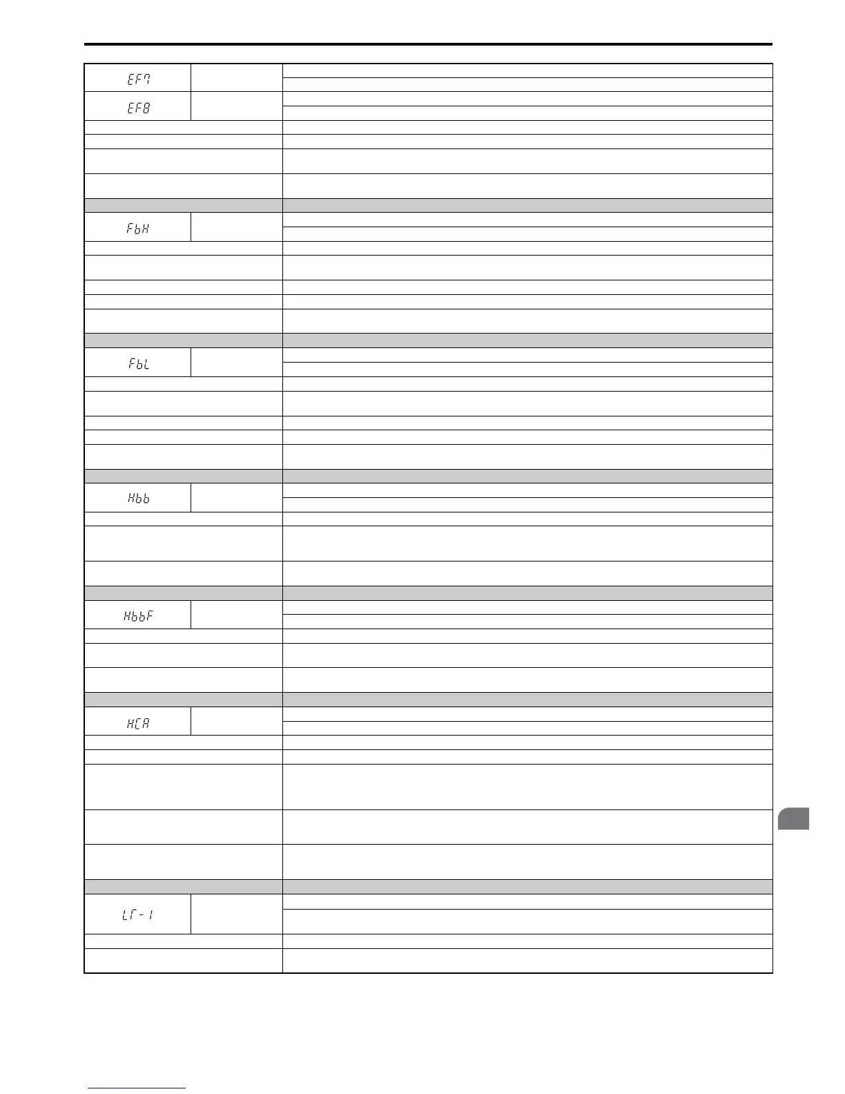
EF7
External fault (input terminal S7)
External fault at multi-function input terminal S7.
EF8
External fault (input terminal S8)
External fault at multi-function input terminal S8.
Cause Possible Solutions
An external device has tripped an alarm function. Remove the cause of the external fault and reset the multi-function input value.
Wiring is incorrect.
• Ensure the signal lines have been connected properly to the terminals assigned for external fault detection (H1- =20to2F).
• Reconnect the signal line.
Multi-function contact inputs are set incorrectly.
• Check if the unused terminals have been set for H1- = 20 to 2F (External Fault).
• Change the terminal settings.
Digital Operator Display Minor Fault Name
FbH
Excessive PID Feedback
The PID feedback input is higher than the level set in b5-36 for longer than the time set in b5-37, and b5-12 is set to 1 or 4.
Cause Possible Solutions
Parameters settings for b5-36 and b5-37 are
incorrect.
Check parameters b5-36 and b5-37.
PID feedback wiring is faulty. Correct the wiring.
Feedback sensor has malfunctioned. Check the sensor and replace it if damaged.
Feedback input circuit is damaged.
Replace either the control board or the entire drive. For instructions on replacing the control board, contact Yaskawa or your nearest
sales representative.
Digital Operator Display Minor Fault Name
FbL
PID Feedback Loss
The PID feedback input is lower than the level set in b5-13 for longer than the time set in b5-14, and b5-12 is set to 1 or 4.
Cause Possible Solutions
Parameters settings for b5-13 and b5-14 are
incorrect.
Check parameters b5-13 and b5-14.
PID feedback wiring is faulty. Correct the wiring.
Feedback sensor has malfunctioned. Check the sensor and replace it if damaged.
Feedback input circuit is damaged.
Replace either the control board or the entire drive. For instructions on replacing the control board, contact Yaskawa or your nearest
sales representative.
Digital Operator Display Minor Fault Name
Hbb
Safe Disable Signal Input
Both Safe Disable Input channels are open.
Cause Possible Solutions
Both Safe Disable Inputs H1 and H2 are open.
• Check signal status at the input terminals H1 and H2.
• Check the Sink/Source Selection for the digital inputs.
• If the Safe Disable function is not utilized, check if the terminals H1-HC, and H2-HC are linked.
Internally, both Safe Disable channels are broken.
Replace either the control board or the entire drive. For instructions on replacing the control board, contact Yaskawa or your nearest
sales representative.
Digital Operator Display Minor Fault Name
HbbF
Safe Disable Signal Input
One Safe Disable channel is open while the other one is closed.
Cause Possible Solutions
The signals to the Safe Disable inputs are wrong or
the wiring is incorrect.
Check signal status at the input terminals H1 and H2. If the Safe Disable function is not utilized, the terminals H1-HC, and H2-HC
must be linked.
One of the Safe Disable channels is faulty.
Replace either the control board or the entire drive. For instructions on replacing the control board, contact Yaskawa or your nearest
sales representative.
Digital Operator Display Minor Fault Name
HCA
Current Alarm
Drive current exceeded overcurrent warning level (150% of the rated current).
Cause Possible Solutions
Load is too heavy. Either reduce the load for applications with repetitive operation (repetitive stops and starts, etc.), or replace the drive.
Acceleration and deceleration times are too short.
• Calculate the torque required during acceleration and for the inertia moment.
• If the torque level is not right for the load, take the following steps:
• Increase the acceleration and deceleration times (C1-01 through C1-08).
• Increase the capacity of the drive.
A special-purpose motor is being used, or the drive is
attempting to run a motor greater than the maximum
allowable capacity.
• Check the motor capacity.
• Use a motor appropriate for the drive. Ensure the motor is within the allowable capacity range.
The current level increased due to Speed Search after
a momentary power loss or while attempting to
perform a fault restart.
The alarm will appear only briefly. There is no need to take action to prevent the alarm from occurring in such instances.
Digital Operator Display Minor Fault Name
LT-1
Cooling Fan Maintenance Time
The cooling fan has reached its expected maintenance period and may need to be replaced.
Note: An alarm output (H2- = 10) will only be triggered if H2- = 2F.
Cause Possible Solutions
The cooling fan has reached 90% of its expected
performance life.
Replace the cooling fan and reset the Maintenance Monitor by setting o4-03 to 0.

 Loading...


