8.5 Installing Peripheral Devices
384 YASKAWA ELECTRIC SIEP C710616 27C YASKAWA AC Drive A1000 Technical Manual
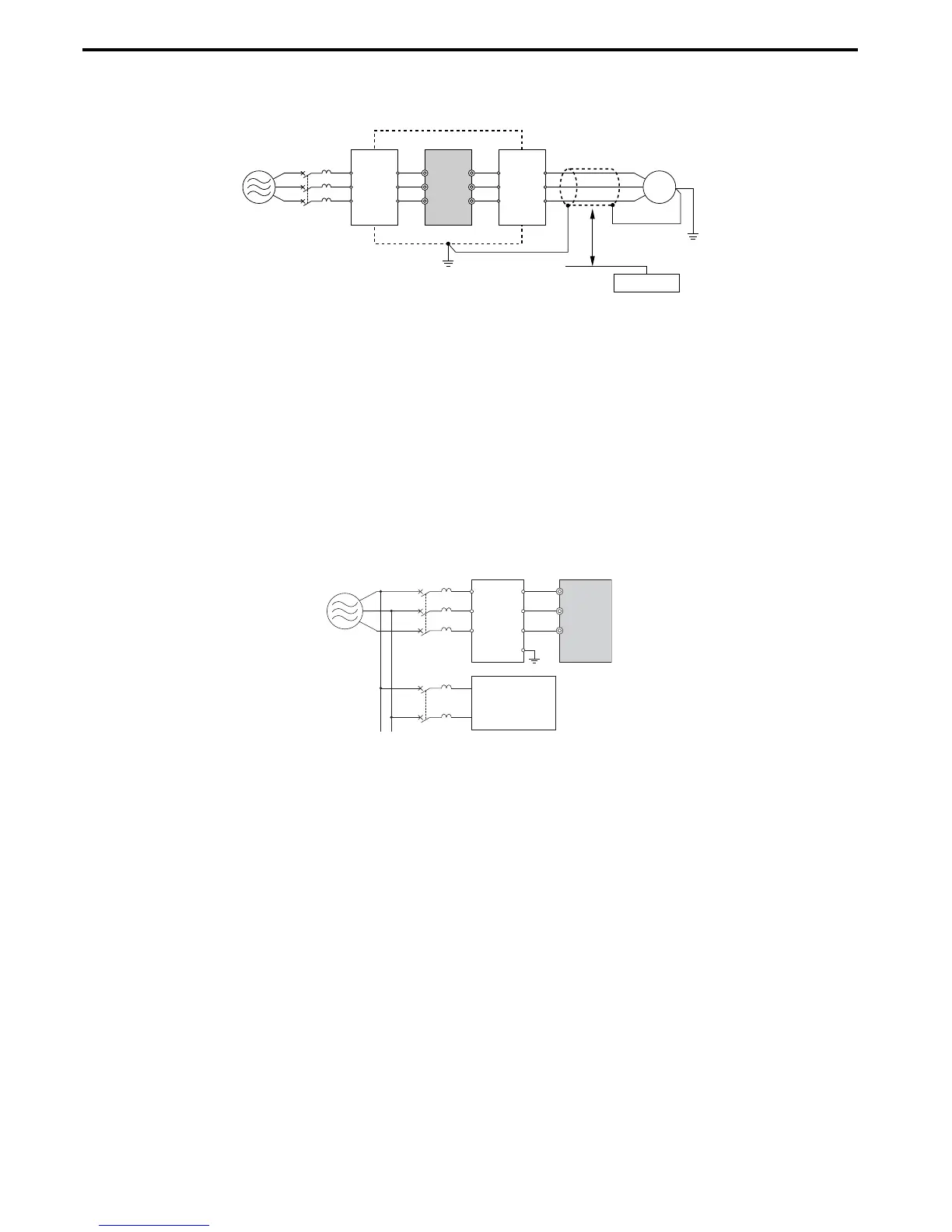
• Use shielded motor and control circuit lines and lay control circuit lines at least 30 cm away from power lines in order
to prevent malfunction due to induced noise.
Figure 8. 13
Figure 8.13 Reducing Radio Frequency Noise
■ Input-Side Noise Filter
Drive outputs generate noise as a result of high-speed switching. This noise flows from inside the drive back to the power
supply, possibly affecting other equipment. Installing a noise filter to the input side of the drive can reduce the amount of
noise flowing back into the power supply. This also prevents noise from entering the drive from the power supply.
• Use a noise filter specifically designed for AC drives.
• Install the noise filter as close as possible to the drive.
Figure 8. 14
Figure 8.14 Input-Side Noise Filter (Three-Phase 200/400 V)
This drive is tested according to European standards IEC61800-5-1 and complies with the EMC guidelines. Refer to
EMC Guidelines Compliance on page 510 for details about EMC filter selection and installation.
■
Output-Side Noise Filter
A noise filter on the output side of the drive reduces inductive noise and radiated noise. Figure 8.15 illustrates an
example of output-side noise filter wiring.
NOTICE: Do not connect phase-advancing capacitors or LC/RC noise filters to the output circuits. Improper application of noise filters
could result in damage to the drive.
A – Metal enclosure F – Shielded motor cable
B – Power supply G – Motor
C – Input noise filter H – Separate at least 30 cm
D – Drive I – Control signal lines
E – Output noise filter J – Controller
A–Power supply C–Drive
B – Input-side noise filter D – Other control device

 Loading...


