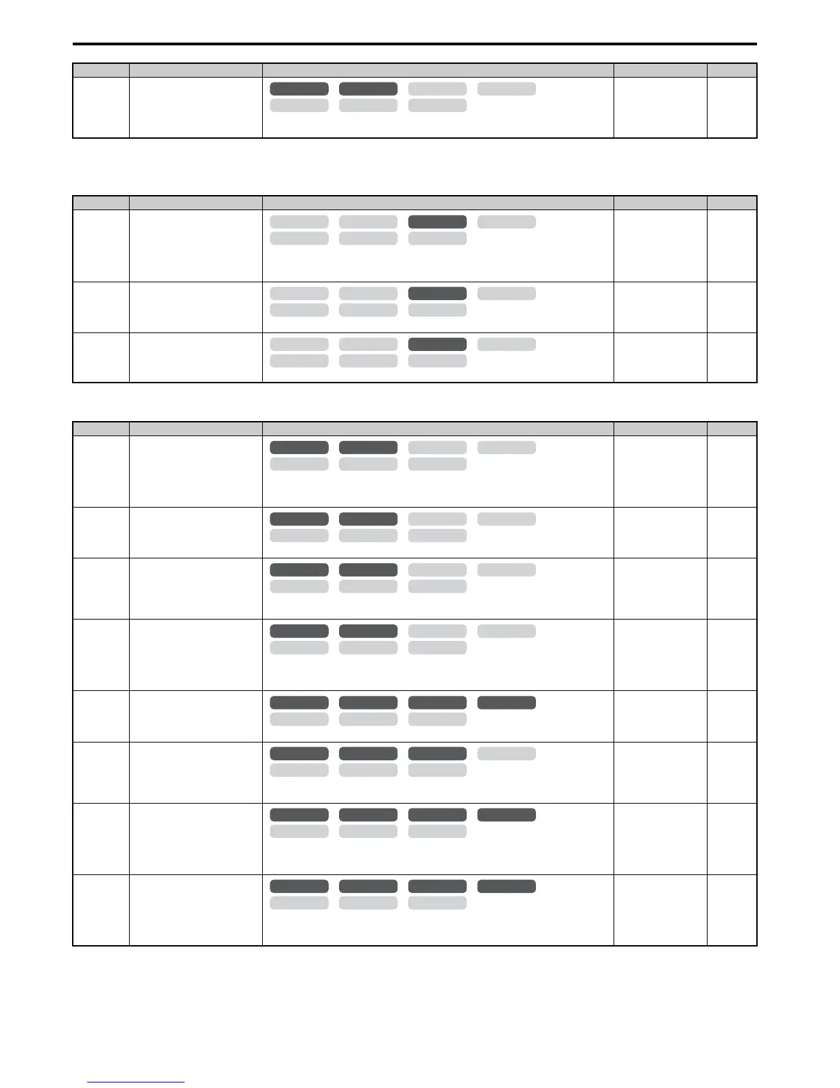
B.3 Parameter Table
440 YASKAWA ELECTRIC SIEP C710616 27C YASKAWA AC Drive A1000 Technical Manual
■ n2: Speed Feedback Detection Control (AFR) Tuning
■ n3: High Slip Braking (HSB) and Overexcitation Braking
n1-05
(530H)
Hunting Prevention Gain while in
Reverse
Sets the gain used for Hunting Prevention. If set to 0, the gain set to n1-02 is used for operation
in reverse.
Default: 0.00
Min: 0.00
Max: 2.50
275
<6> Default setting value varies by the drive model (o2-04).
No. (Addr.) Name Description Setting Page
n2-01
(584H)
Speed Feedback Detection Control
(AFR) Gain
Sets the internal speed feedback detection control gain in the automatic frequency regulator
(AFR).
If hunting occurs, increase the set value. If response is low, decrease the set value.
Default: 1.00
Min: 0.00
Max: 10.00
276
n2-02
(585H)
Speed Feedback Detection Control
(AFR) Time Constant 1
Sets the time constant used for speed feedback detection control (AFR).
Default: 50 ms
Min: 0 ms
Max: 2000 ms
276
n2-03
(586H)
Speed Feedback Detection Control
(AFR) Time Constant 2
Sets the AFR time constant to be used during Speed Search and during regen.
Default: 750 ms
Min: 0 ms
Max: 2000 ms
276
No. (Addr.) Name Description Setting Page
n3-01
(588H)
<35>
The upper limit of the setting range is determined by the values set to duty selection (C6-01) and the carrier frequency reduction selection (L8-38).
High Slip Braking Deceleration
Frequency Width
Sets the output frequency reduction step width for when the drive stops the motor using HSB.
Set as a percentage of the maximum output frequency. Increase this setting if overvoltage
occurs during HSB.
Default: 5%
Min: 1%
Max: 20%
276
n3-02
(589H)
High Slip Braking Current Limit
Sets the current limit during HSB as a percentage of the motor rated current.
Default:
<35>
Min: 100%
Max: 200%
277
n3-03
(58AH)
High Slip Braking Dwell Time at
Stop
Sets the time the drive will run with minimum frequency (E1-09) at the end of deceleration.
If this time is set too low, the machine inertia can cause the motor to rotate slightly after HSB.
Default: 1.0 s
Min: 0.0 s
Max: 10.0 s
277
n3-04
(58BH)
High-Slip Braking Overload Time
Sets the time required for an HSB overload fault (oL7) to occur when the drive output
frequency does not change during an HSB stop. This parameter does not typically require
adjustment.
Default: 40 s
Min: 30 s
Max: 1200 s
277
n3-13
(531H)
Overexcitation Deceleration Gain
Sets the gain applied to the V/f pattern during Overexcitation Deceleration (L3-04 = 4).
Default: 1.10
Min: 1.00
Max: 1.40
278
n3-14
(532H)
High Frequency Injection during
Overexcitation Deceleration
0: Disabled
1: Enabled
Default: 0
Min: 0
Max: 1
278
n3-21
(579H)
High-Slip Suppression Current
Level
Sets output current level at which the drive will start reducing the overexcitation gain in order to
prevent a too high motor slip during Overexcitation Deceleration. Set as a percentage of the
drive rated current.
Default: 100%
Min: 0%
Max: 150%
278
n3-23
(57BH)
Overexcitation Operation
Selection
0: Enabled in both directions
1: Enabled only when rotating forward
2: Enabled only when in reverse
Default: 0
Min: 0
Max: 2
278
No. (Addr.) Name Description Setting Page
OLV/PM AOLV/PM
CLV
V/f w/PG
CLV/PM
V/f OLV

 Loading...


