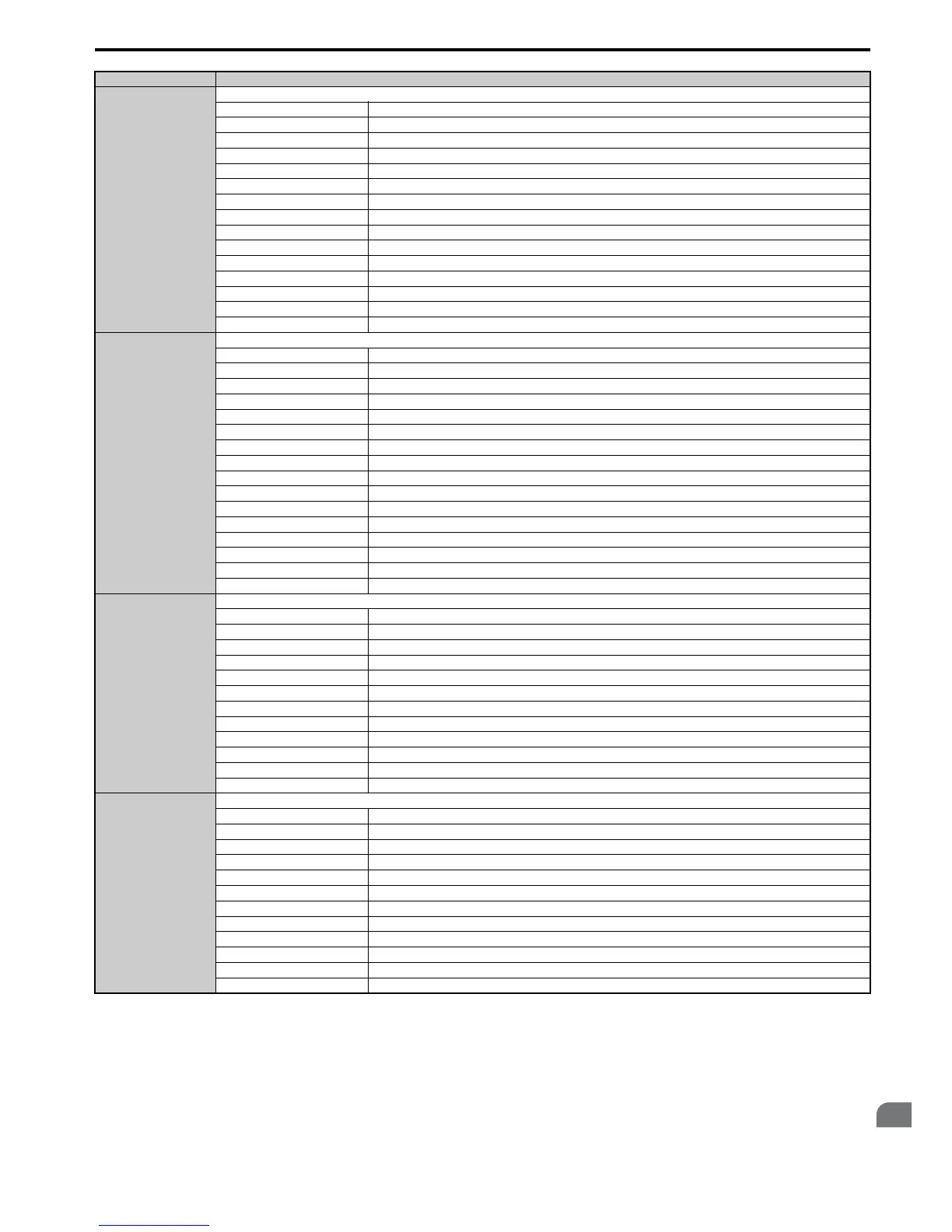
00C0H
Fault contents 3
bit 1 Undervoltage (Uv1)
bit 2 Control Power Supply Undervoltage (Uv2)
bit 3 Soft Charge Circuit Fault (Uv3)
bit 4 Reserved
bit 5 Ground Fault (GF)
bit 6 Overcurrent (oC)
bit 7 Overvoltage (ov)
bit 8 Heatsink Overheat (oH)
bit 9 Heatsink Overheat (oH1)
bit A Motor Overload (oL1)
bit B Drive Overload (oL2)
bit C Overtorque Detection 1 (oL3)
bit D Overtorque Detection 2 (oL4)
bit E Dynamic Braking Transistor Fault (rr)
bit F Braking Resistor Overheat (rH)
00C1H
Fault contents 4
bit 0 External Fault at input terminal S3 (EF3)
bit 1 External Fault at input terminal S4 (EF4)
bit 2 External Fault at input terminal S5 (EF5)
bit 3 External Fault at input terminal S6 (EF6)
bit 4 External Fault at input terminal S7 (EF7)
bit 5 External Fault at input terminal S8 (EF8)
bit 6 Cooling Fan Error (FAn)
bit 7 Overspeed (os)
bit 8 Excessive Speed Deviation (dEv)
bit 9 PG Disconnected (PGo)
bit A Input Phase Loss (PF)
bit B Output Phase Loss (LF)
bit C Motor Overheat (PTC input) (oH3)
bit D Digital Operator Connection Fault (oPr)
bit E EEPROM Write Error (Err)
bit F Motor Overheat Fault (PTC input) (oH4)
00C2H
Fault contents 5
bit 0 MEMOBUS/Modbus Communication Error (CE)
bit 1 Option Communication Error (bUS)
bit 2, 3 Reserved
bit 4 Control Fault (CF)
bit 5 Zero Servo Fault (SvE)
bit 6 Option External Fault (EF0)
bit 7 PID Feedback Loss (FbL)
bit 8 Undertorque Detection 1 (UL3)
bit 9 Undertorque Detection 2 (UL4)
bit A High Slip Braking Overload (oL7)
bit B to E Reserved
bit F Hardware Fault (includes oFx)
00C3H
Fault contents 6
bit 0 Reserved
bit 1 Z Pulse Fall Detection (dv1)
bit 2 Z Pulse Noise Fault Detection (dv2)
bit 3 Inversion Detection (dv3)
bit 4 Inversion Prevention Detection (dv4)
bit 5 Current Imbalance (LF2)
bit 6 Pullout Detection (STo)
bit 7 PG Hardware Fault (PGoH)
bit 8 SI-T3 Watchdog Error (E5)
bit 9 Reserved
bit A Too many speed search restarts (SEr)
bit B to F Reserved
Register No. Contents

 Loading...


