Connect control wires as shown in the following figure:
Figure 3.29
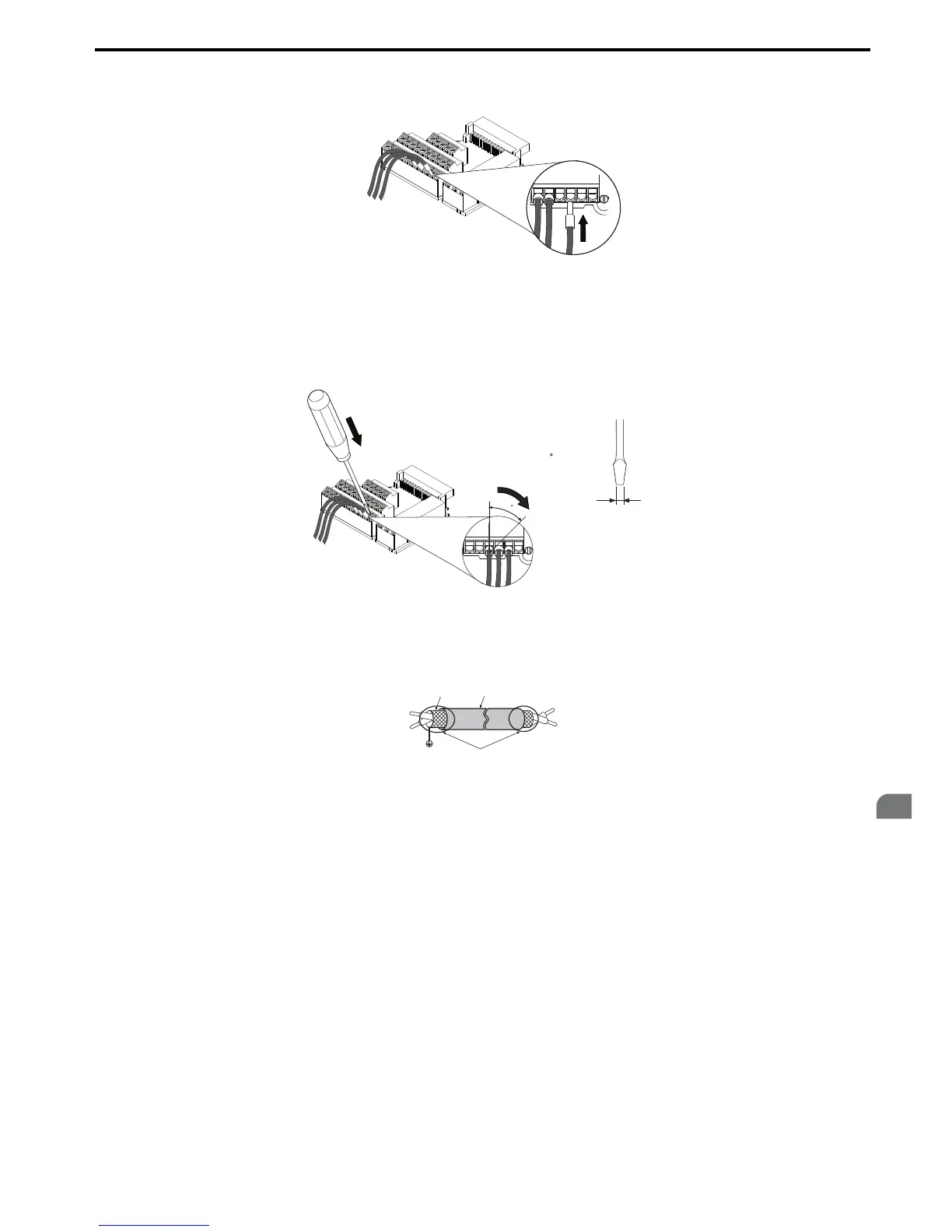
Figure 3.25 Terminal Board Wiring Guide
To disconnect control wires from the terminals use the procedure described in Figure 3.26. Grasp the wire where it
enters the terminal with a pair of pliers, then use a straight-edge screw driver to release the terminal and pull the wire out.
If it fits tightly, e.g. if ferrules are used, turn the wire for about 45° and then pull it gently out. Use this procedure to
remove the wire jumper between terminals HC, H1 and H2 that is preinstalled at shipping.
Figure 3.30
Figure 3.26 Removing Wires from the Terminal Board
When setting the frequency by analog reference from an external potentiometer, use shielded twisted-pair wires (treating
wire ends as shown in Figure 3.27 and connect the shield to the ground terminal of the drive.
Figure 3.31
Figure 3.27 Preparing the Ends of Shielded Cables
NOTICE: The signal lines between the drive and the operator station or peripheral equipment should not exceed 50 meters when
using an analog signal from a remote source to supply the frequency reference. Failure to comply could result in poor system
performance.
A – Drive side D – Control device side
B – Connect shield to ground terminal of
drive.
E – Shield sheath (insulate with tape)
C – Insulation F – Shield

 Loading...


