1 Equipment Configuration
DX100 1.1 Arrangement of Units and Circuit Boards
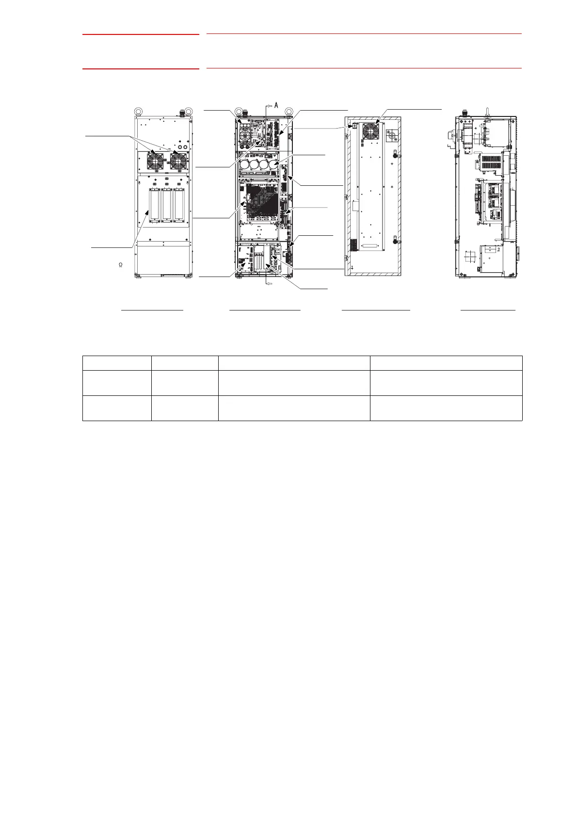
1-3
Fig. 1-3: Configuration of Large Capacity DX100 -A Controller (Standard)
A’
(1500W 6.0 )
SMVK500W2R0J
A5978 X3
JZNC-YPS01-E
CPS Unit
Robot I/Fcircuit board
JANCD-YIF01-1
CPU Unit
JZNC-YRK01-E
NF32-SW
JZNC-YSU01-1E
JZRCR-YPU01-1
A-A’ Section
Inside View of F Door
Front View
Inside the Controller
Back View
(without cover)
Interior circulation fan:
4715MS-22T-B50-B00
(For air inlet)
I/O Unit
JZNC-YIU01-E
Converter
Refer to the
following table.
Emergency stop
button:
HW1B-V404R
Brake board
JANCD-YBK01-1E
Machine safety unit
(MXT)
Robot system
specified input
terminal block
Regenerative
registor
Backside duct fan:
4715MS-22T
-B50-B00
(For air inlet)
Breaker
Power supply
contactor unit
SERVOPACK:
Refer to the
following table.
Model DX100 SERVOPACK Converter
ES165D ERDR-
ES0165D-A00
SRDA-MS165 SRDA-COA30A01A-E
ES200D ERDR-
ES0200D-A00
SRDA-MS165 SRDA-COA30A01A-E

 Loading...


