5 Replacing Parts
DX100 5.1 Replacing DX100 Parts
5-5
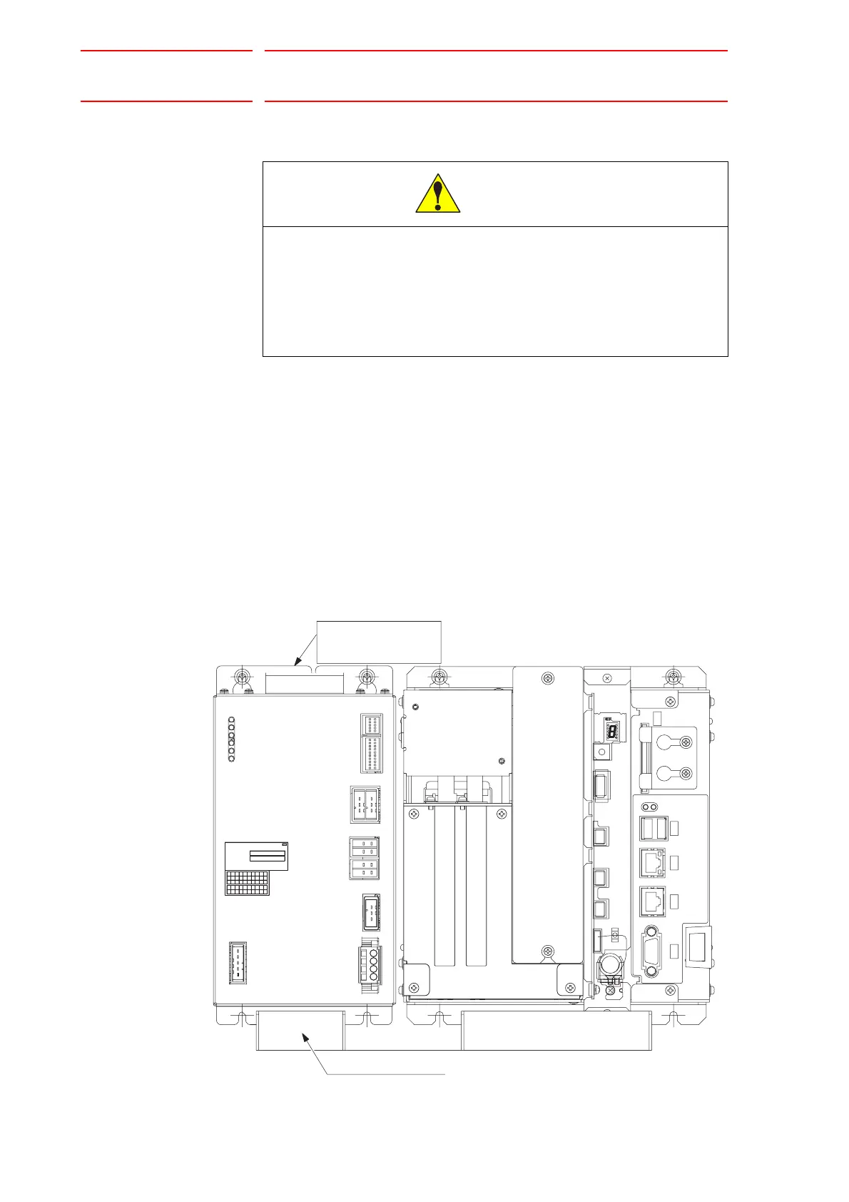
5.1.1.3 Replacing the Control Power Supply (JZNC-YPS01-E)
Replacement Procedure
1. Disconnect all cables connected to the CPS unit.
2. Loosen upper screws (2 places) fixing the CPS unit to the controller.
3. Hold to remove the CPS unit itself by pulling out the power supply from
the controller.
4. Insert the lower part flange of the new CPS unit into the fixing jig which
is at the bottom of the controller.
5. Tighten upper screws.
6. Connect all the disconnected cables.
CAUTION
• After turning OFF the power supply, wait at least 5 minutes
before replacing a control power supply. Do not touch any
terminals during this period. Confirm all monitor lights are
turned OFF.
Failure to observe this caution may result in electric shock or injury.
CN107
CN106 CN105 CN104 CN103
V
U
T
S
R
Q
P
N
M
L
K
J
H
G
F
E
DC
BA
30
29282726
14
25242322
21
20
19181716151312
11
10
0908070605040302
01
C90AD XXXXX
MADE IN JAPAN
Fuji Electric Hi-Tech Corp.
DATE
NO.
POWER SUPPLY
CPS-520F
YYYY-MM
V
U
T
S
R
Q
P
N
M
L
K
J
H
G
F
E
DC
BA
30
29282726
14
25242322
21
20
19181716151312
11
10
0908070605040302
01
CN154
(+24V1/+24V2)
CN159
CN158
(+5V)
CN155
(+24V1/+24V2)
(+24V2)
CN156/157
(+24V3)
CN153
(REMOTE)
CN152
(ALM)
SOURCE
OHT
INPUT
FAN
+24V
+5V
P-ON
50/60Hz
(AC IN)
CN151
200-240V AC
3.4A-2.8A
Controll Power supply
JZNC-YPS01-E
CPS UNIT(YPS)
Fixing jig for the flange

 Loading...


