5 Replacing Parts
DX100 5.1 Replacing DX100 Parts
5-18
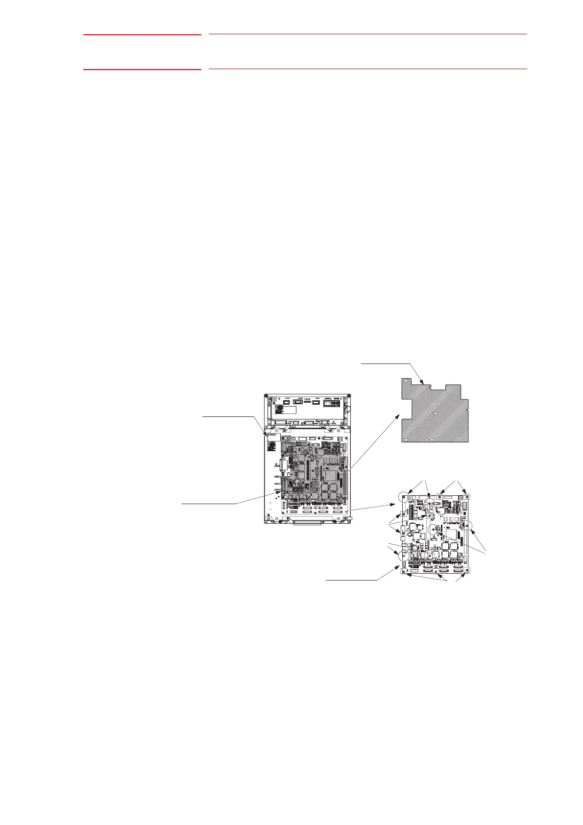
5.1.4 Replacing the Basic Axis Control Circuit Board (SRDA-EAXA01A)
Turn OFF the power before replacing the circuit board.
1. Disconnect all the cables connected to the circuit board.
2. Remove A screws. (6 places)
3. Remove the EAXA cover.
4. Remove hexagon threaded spacers (6 places) fixing A screws.
5. Remove B screws (8 places).
6. Remove the control circuit board from the SERVOPACK.
7. Install the new circuit board to the SERVOPACK in the reverse order of
the removing procedure.
8. Set the rotary switch to the same value as the removed circuit board’s
rotary switch.
9. Reinstall the EAXA cover.
10. Connect all the disconnected cables in the step 1.
Basic Axis Control Circuit Board Replacement Procedure
EAXA Board
B ScrewA Screw
EAXA Cover
SERVOPACK
EAXA Cover
A Screw
A Screw
B Screw
B Screw

 Loading...


