5 Replacing Parts
DX100 5.1 Replacing DX100 Parts
5-10
5.1.1.7 Replacing the Brake Board (JZRCR-YBK01-E)
Replacement Procedure
1. Disconnect the cable connectors connected to the brake board.
*Do not disconnect jumper wiring connectors at CN404 yet.
(Disconnect the ground wirings screwed to the front side of the board.)
2. Loosen upper and lower side screws (4 places) fixing the brake board
to the controller.
3. Remove the brake board from the controller by holding up upper and
lower side cover.
4. Hook the new brake board to the screws in the controller (4 places).
5. Tighten upper and lower side screws (4 places) to fix the brake board.
6. Disconnect CN404 jumper wiring connectors from the removed brake
board and connect them toCN404 on the new brake board.
7. Connect all the disconnected cables in the order of CN400,CN402,
CN403 AND CN405.
(Connect the ground wirings firmly.)
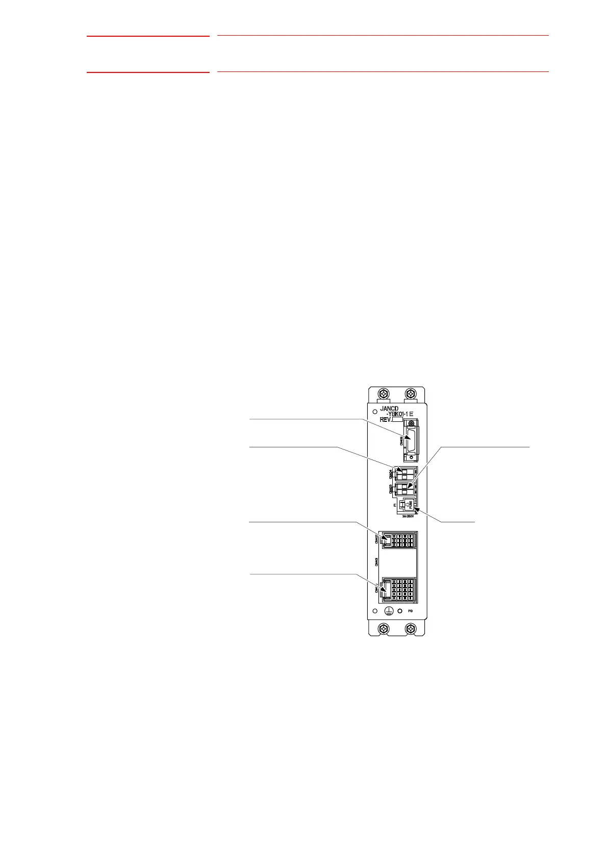
Brake board (JANCD-YBK01-
E)
F1: Fuse
3A/250V
(CN405)
Brake command input connector
(CN404)
Connector for switching
the external power supply
(CN403)
Connector for brake power
supply input
Brake output connector
(CN400)
(CN402)
Contactor interlock input connector

 Loading...


