5 Replacing Parts
DX100 5.1 Replacing DX100 Parts
5-16
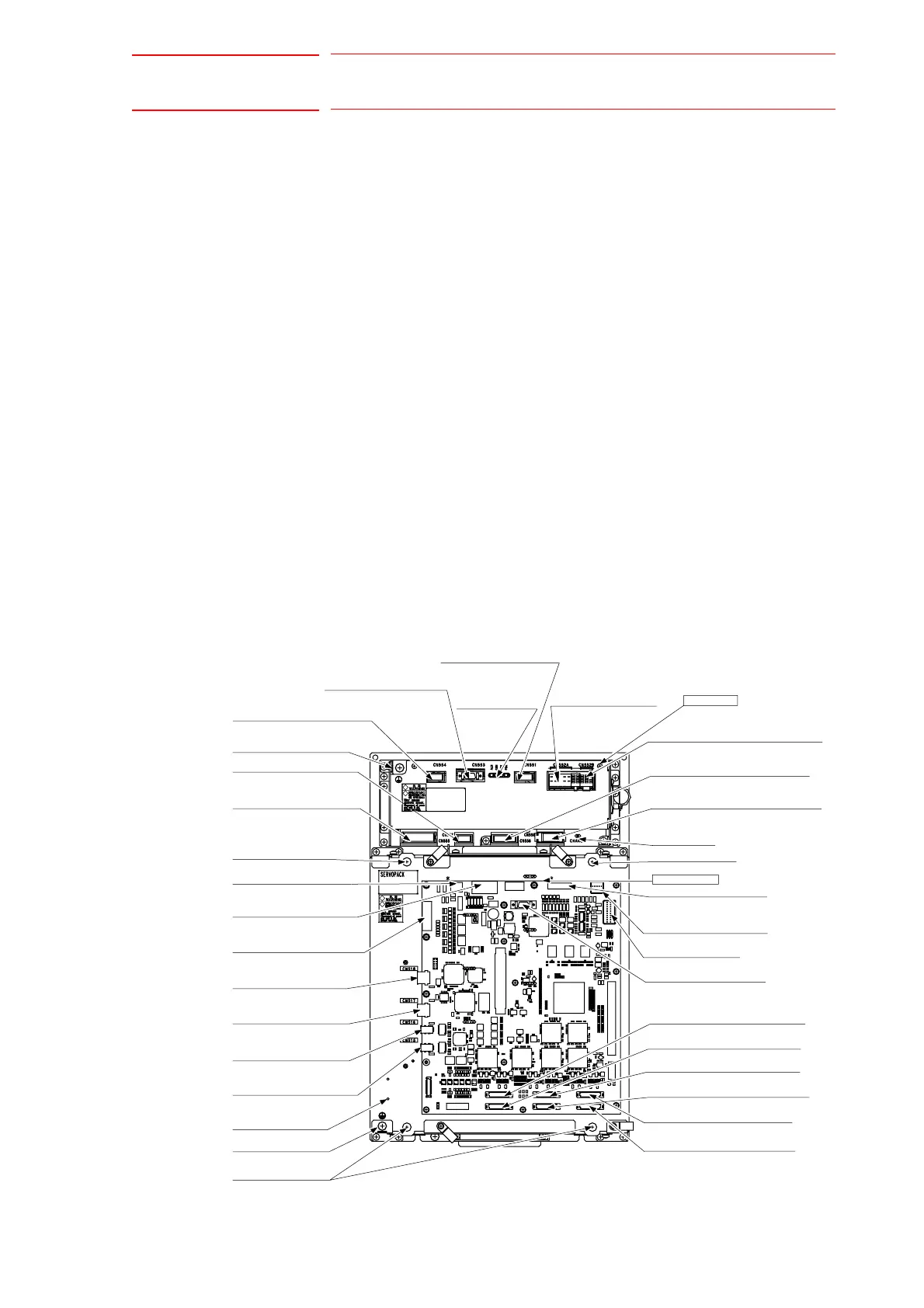
(4) Control power supply output connector for 6-axis amplifier
(CN552A)
(5) Control power supply input connector (CN551)
(6) Brake control signal connector (CN513)
(7) Control power supply input connector (CN509)
(8) SHOCK signal input connector (CN512)
(9) Ground terminal connectors (EAXA base)
(10) Control communication connector (CN515)
(11) I/O communication connector (CN517)
(12) Encoder signal connector (CN508)
4. Put the disconnected cable to the right side of the SERVOPACK.
5. Unscrew two EAXA base fixing screws. (lower side)
6. Unscrew two EAXA base fixing screws. (upper side)
7. Open the EAXA base.
8. Disconnect all the cables connected to the amplifier to be replaced.
(1) Main circuit power supply input connector (CN555)
(2) Regeneration register connecting connector (CN557)
(3) Main circuit power supply output connector for 6-axis amplifier
(CN556)
9. Remove the ground wiring connected to the converter.
10. Remove 4 screws fixing the converter.
11. Hold the top grip and lift it to pull out the converter.
12. Install the new converter and reconnect the connectors in the reverse
order of the removing procedure.
(Connect the ground wirings firmly.)
Integrated SERVOPACK
Connector for connecting
regenerative resistor
EAXA base fixing
screw (upper)
Connector for converter
control signal
Connector for
grounding detection input
Ground terminal
Connector for main
circuit power supply input
EAXA base fixing
screw (upper)
SHOCK signal input
connector
Connector for control
power supply input
Connector for encoder
signal
I/O communication
connector
I/O communication
connector
Control communication
connector
Control communication
connector
EAXA base
EAXA base fixing
screw (bottom)
(CN513)
(CN507)
(CN511)
(CN514)
AMP2 PWM Signal connector
(CN502)
(CN501)
AMP1 PWM Signal connector
AMP3 PWM Signal connector
(CN503)
AMP4 PWM Signal connector
(CN504)
AMP6 PWM Signal connector
AMP5 PWM Signal connector
(CN505)
(CN506)
EAXA Board
(CN552B)
Converter
(CN556)
(CN558)
(CN516)
(CN518)
(CN512)
Grounding terminal
(CN517)
(CN515)
(CN508)
(CN509)
(CN551)
(CN552A)
(CN557)
(CN555)
(CN554)
(CN553)
Connector for converter
control signal
Direct-in connector
Safety unit I/F connector
Connector for break
control signal
Charge lamp
Main circuit power supply output
connector for external axis amplifie
Main circuit power supply output
connector for 6-axis amplifier
Control power supply output
connector for external axis amplifier
Connector for control
power supply input
Control power supply
output connector for
6-axis amplifier
Monitor/Alarm
displaying LED

 Loading...


