3-24
IM 701240-01E
• Fot the 701267 (HV (with RMS))
Maximum input voltage (at a frequency of 1 kHz or less)
• Combination of 758933 measurement leads and 701954 alligator clips
3
850 V (DC+ACpeak)
• Direct input (cable that does not comply with the safety standards)
6
42 V (DC+ACpeak)
Maximum allowable common mode voltage (at a frequency of 1 kHz or less)
• Combination of 758933 measurement leads and 701954 alligator clips
5
(Use caution because the overvlotage tolerance differs between the low and
high sides.)
700 Vrms (CAT II) on the H side
4
, 400 Vrms (CAT II)
5
on the L side
• Direct input (cable that does not comply with the safety standards)
7
42 V (DC+ACpeak) (CAT II, 30 Vrms)
H
L
1
2
(Red)
(Black)
H
L
3
5
(Red)
(Black)
758933 701954
4
H
L
6
7
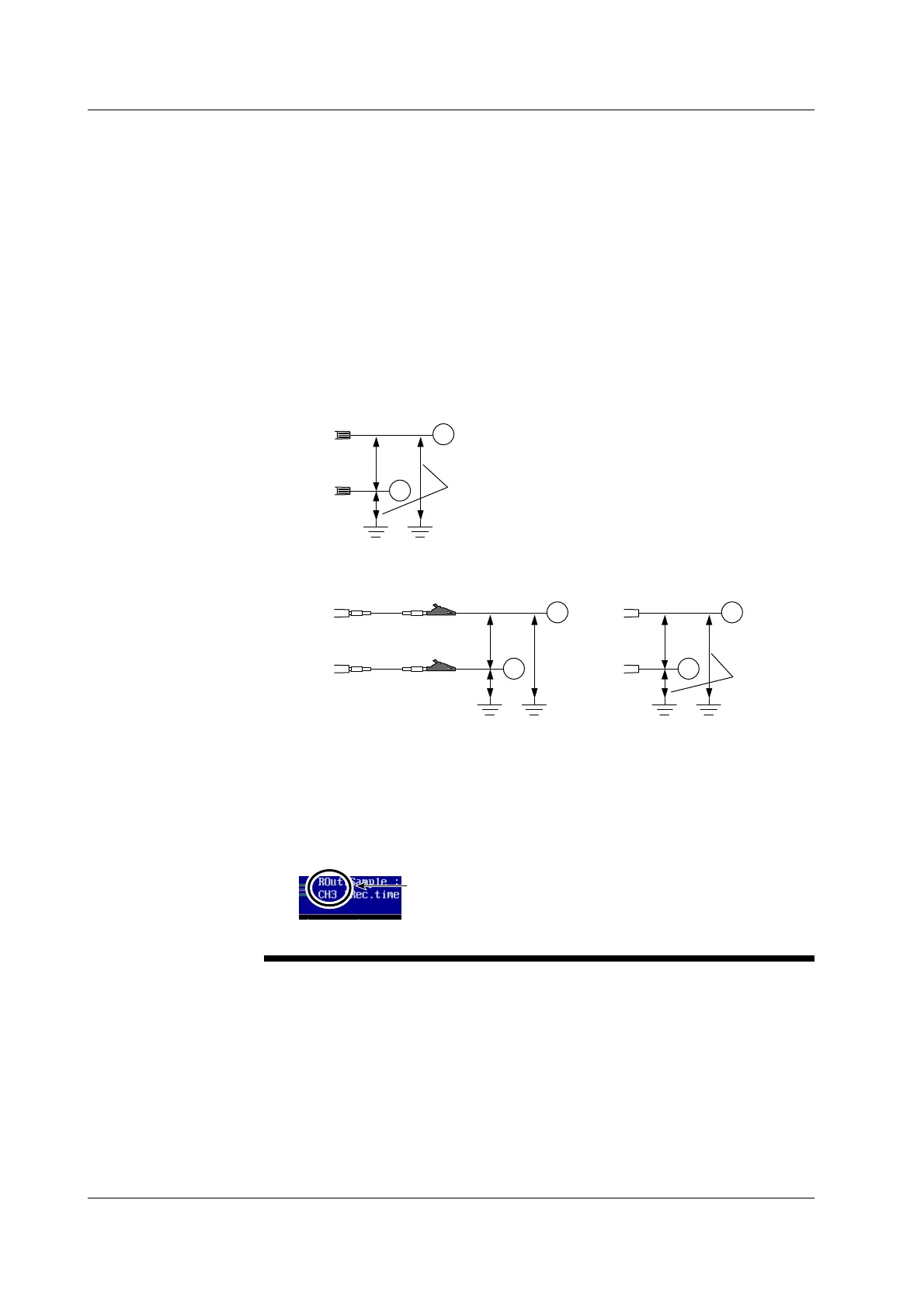
For the 701261, 701262, and 70126
For the 701267
With the 758933 and 701954
Input
terminal
Input
terminal
(Red)
(Black)
Input
terminal
Direct input (cable that does not
comply with the safety standards)
Over-Range Indication
If over-range is indicated, the SL1400 may be receiving a voltage higher than
the observed waveform or measured waveform values. To prevent electric
shock, change the vertical scale with the RANGE knob so that the entire
amplitude of the waveform is displayed within the waveform display area, and
check the input voltage level.
Over-range indication
Indicates the number of the channel that over-range is occurring on.
If over-range is occurring on multiple channels, the smallest channel
number among them is indicated.
3.11 Connecting Measurement Leads

 Loading...


