2-1
IM 701240-01E
2
1
4
5
6
7
8
9
10
11
12
13
14
15
16
17
18
App
Index
Explanation of Functions
2.1 System Configuration and Block Diagram
System Configuration
Signal input
Device under
measurement
• Module
1
• Probe
2
• Mesurement lead
Personal
computer
(PC)
USB printer
Printer
PC card
External SCSI device
(MO, Zip drive, etc.)
USB keyboard
Built-in printer
(rear panel)
• External clock input
• External trigger input
• Video signal output
• Trigger output
Save/Load data
• Waveform data
• Setup data
• Screen data
Screen data
USB PERIPHERAL
interface
• GP-IB interface
• RS-232 interface
• USB interface
(Remote control through
command communications)
• SCSI
(data download)
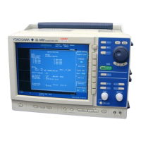
SL1400
1 • High-Speed 10 MS/s, 12-Bit
Isolation Module
• High-Speed High-Resolution
1 MS/s, 16-Bit Isolation Module
• High-Speed 10 MS/s, 12-Bit
Non-Isolation Module
• High-Voltage 100 kS/s, 16-Bit
Isolation Module (with RMS)
• Temperature, High Precision
Voltage Isolation Module
• Universal (Voltage/Temp.) Module
• Universal (Voltage/Temp.) Module
(with AAF)
• Strain Module (NDIS)
• Strain Module (DSUB, Shunt-Cal)
• Acceleration/Voltage Module
(with AAF)
• Frequency Module
2 • Differential probe
• Current probe
•
Logic probe
Built-in HDD (option)
USB mouse
Shared HDD
Ethernet interface (option)
PC
Network printer
FTP
server
• FTP server
• FTP client
• Web server
Printer
server
Printer
SCSI
USB storage device
(MO, HDD, or flash memory)
USB PERIPHERAL
interface
Chapter 2 Explanation of Functions

 Loading...


