Analog Duplex System
Subject to Export Control, see Cover Page for details.
8-4
Analog Duplex Configuration Tiles
The Analog Duplex Configuration Menu allows test parameters to be defined for customized user
specifications. Analog Duplex consists of the following Configuration Tiles:
Offsets Configuration Tile
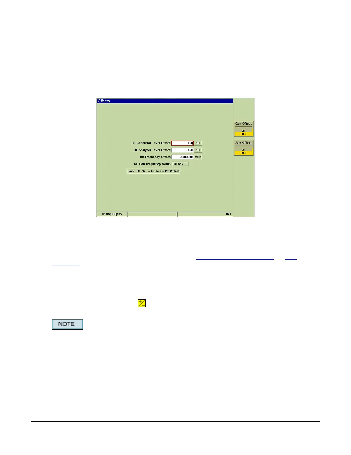
The Offsets Tile contains fields that define offset values for the level and frequency offsets for the
RF Generator.
Fig. 8-3 Analog Duplex - Offsets Configuration Tile
Field/Soft Key Definitions
RF Generator Level Offset
The RF Generator Level Offset parameter accounts for a loss or gain to be inserted into the RF
path between the 3900 generator output connector (GEN (Generator) Connector
or T/R
Connector) and the device under test.
The Offset value is indicated in +dB for positive (gain) values. When a positive value is entered,
Ext Gain is displayed to the right of the RF Generator Level Offset value field.
The Offset value is indicated in -dB for negative (loss) values. When a negative value is entered,
Ext Loss is displayed to the right of the RF Generator Level Offset value field.
When an offset is enabled, the warning symbol is shown beside the output level entry field on
the Generator Tile.
Level Offsets set in the Analog Duplex system are independent of any Level Offsets set in
any other System on the Test Set.