Test Set Operation
Subject to Export Control, see Cover Page for details.
3-57
Receiver and Transmitter Testing
To test a ‘Stand alone’ receiver or transmitter, use the RF IN/OUT soft key(s) to select the
Connector best suited to the specification of the equipment under test. The desired RF input and
output connectors are selected from the Test System. For transmitter testing, the RF Gen output
may need to be disabled.
There are four possible arrangements described in this section.
Overload Warning
If the RF Signal applied to the ANT (Antenna) Connector exceeds the safe maximum level, an
audible and visual warning is triggered. The overload warning is also triggered if excessive
reverse power is applied to the GEN (Generator) Connector.
One Port Duplex
The One Port Duplex arrangement uses the T/R Connector for RF input and RF output. This
arrangement is typically used for testing mobile radios via a single direct connection to the
radio’s antenna connection. This arrangement can also be used for off air testing of radios when
only a single antenna is available, or for testing Base stations that use a combined Rx/Tx
antenna system.
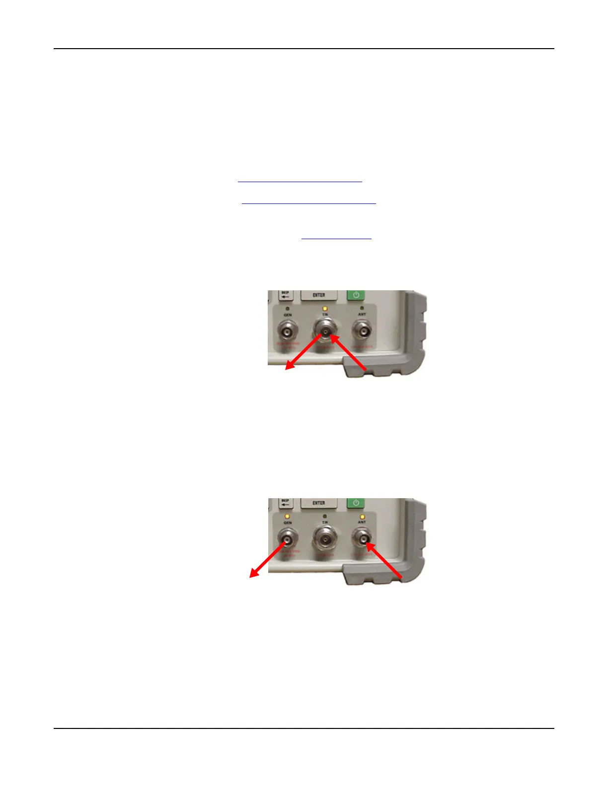
Fig. 3-58 One Port Duplex Test Setup
Two Port Duplex
There are three types of Two Port Duplex setups which can be used for measuring RF Gen output
and RF Analyzer input.
GEN/ANT
This Two Port Duplex arrangement provides the highest level of RF Gen output and the most
sensitive RF Analyzer input. This setup is useful for ‘Off Air’ testing of radios with separate
antennas.
Fig. 3-59 GEN/ANT Two Port Duplex Test Setup
RF Out = T/R
RF In = T/R
RF Out = GEN
RF In = ANT