Installation
Subject to Export Control, see Cover Page for details.
2-8
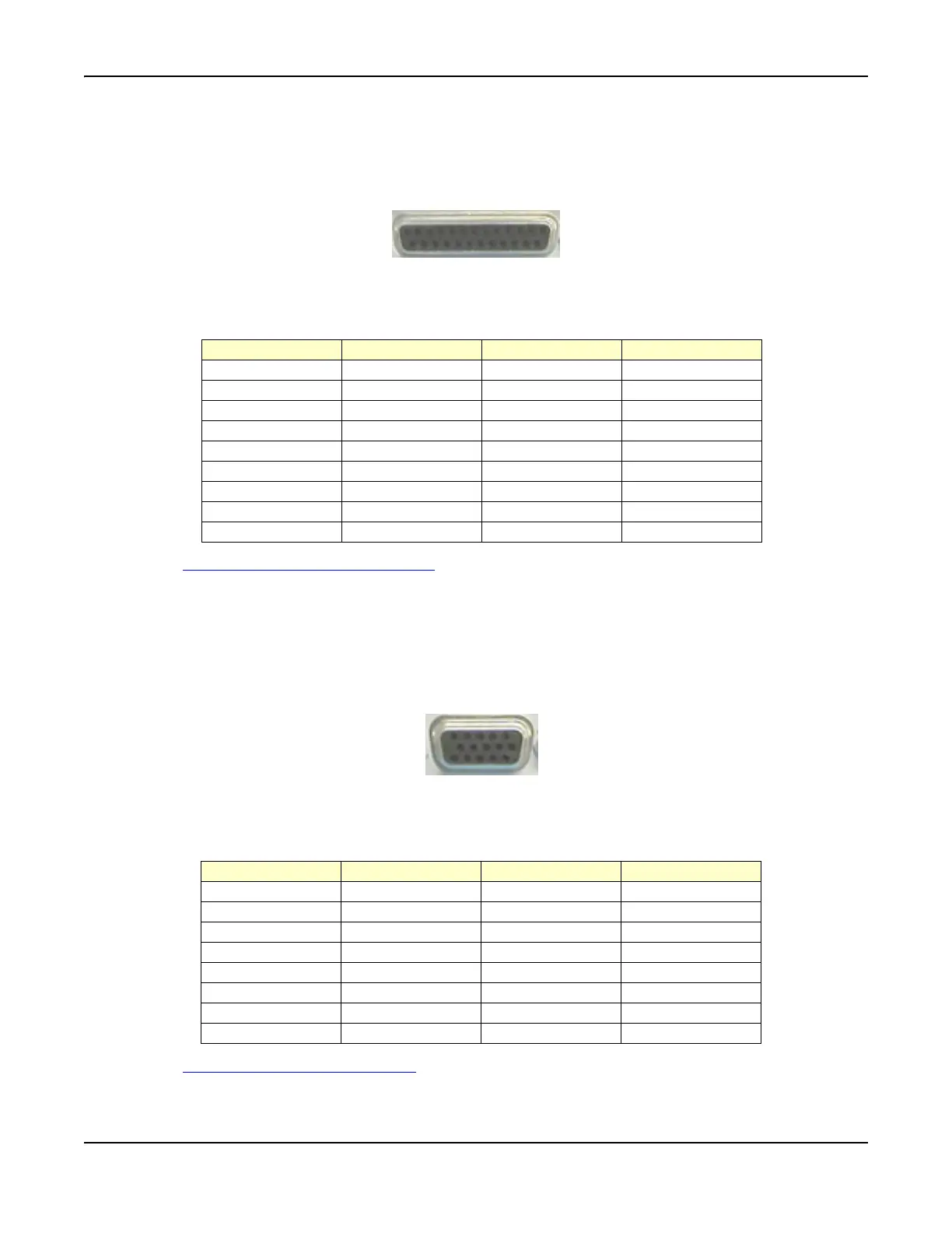
Parallel Connector
The Parallel Connector has a 25-way D-type socket mounted on the rear panel. Refer to Fig. 2-8 for
pin locations.
Fig. 2-8 Parallel Connector Pin Locations
Parallel Connector pin functions are as follows:
See also Parallel Printer Output Connector
in Chapter 3, Test Set Operation.
Aux IF Input
This connector is reserved for future development.
VGA Monitor Output
The VGA Output is a 15-way ‘D’ type connector on the rear panel. Refer to Fig. 2-9 for pin locations.
Fig. 2-9 VGA Monitor Output Pin Locations
VGA Monitor Output pin functions are as follows:
See also VGA Monitor Output Connector in Chapter 3, Test Set Operation.
113
25
14
Pin Number Function Pin Number Function
1 Strobe 10 ACK
2 Data 0 11 BUSY
3 Data 1 12 PE
4 Data 2 13 SLCT
5 Data 3 14 AUTOFD
6 Data 4 15 ERROR
7 Data 5 16 INIT
8 Data 6 17 SLCT IN
9 Data 7 18 to 25 Ground
1
5
610
15 11
Pin Number Function Pin Number Function
1 Red Video 9 No Connection
2 Green Video 10 Sync Return
3 Blue Video 11 Monitor ID 0
4 Monitor ID 2 12 Monitor ID 1
5 Ground 13 Horizontal Sync
6 Red Return 14 Vertical Sync
7 Green Return 15 Monitor ID 3
8 Blue Return