Analog Duplex System
Subject to Export Control, see Cover Page for details.
8-8
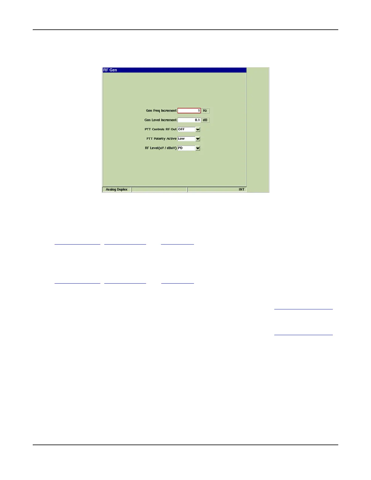
RF Generator Configuration Tile
The RF Generator Tile contains fields that define RF Generator parameters.
Fig. 8-6 Analog Duplex - RF Generator Configuration Tile
Field Definitions
Gen Frequency Increment
Sets the value the RF Output Frequency changes each time the [INC Gen Freq/DEC Gen Freq]
Soft Keys are pressed. The [INC Gen Freq/DEC Gen Freq] Soft Keys are located on the
Generators Tile, Analyzers Tile and Meters Tile. This soft key is accessed by pressing the [INC/
DEC] soft key. Value is specified in MHz, kHz or Hz as defined by user.
Gen Level Increment
Sets the value in dB, that the RF Level changes each time the [INC Gen Level/DEC Gen Level]
Soft Keys are pressed. The [INC Gen Level/DEC Gen Level] soft Keys are located on the
Generators Tile
, Analyzers Tile and Meters Tile The soft key is accessed by pressing the [INC/
DEC] soft key. Value is specified in MHz, kHz or Hz as defined by user.
PTT Controls RF Out
This feature is only applicable when a microphone is connected to the 3900 MIC/ACC Connector.
When ON is selected PTT must be pressed to utilize the RF Output.
PTT Polarity Active
This feature is only applicable when a microphone is connected to the 3900 MIC/ACC Connector.
High or Low polarity is applied to the signal when PTT is pressed.
RF Level
Selects whether the RF Generator Output Level, when given in μ V (micro Volt) is expressed in a
PD or EMF reference system.
μV (PD) = micro Volts Potential Difference
This circuit is closed onto a matching load that is equal to the output impedance of the
source. The PD reference system includes a voltage 1:2 divider at the load.
μV (EMF) = micro Volts Electromotive Force
This circuit is open, or closed onto an infinite load. The EMF reference system does not
contain a voltage divider at the load, resulting in values two times larger than those in the PD
reference system. For example, -120 dBm is equal to 0.225 μ V (PD) or 0.45 μ V (EMF).