Installation
Subject to Export Control, see Cover Page for details.
2-11
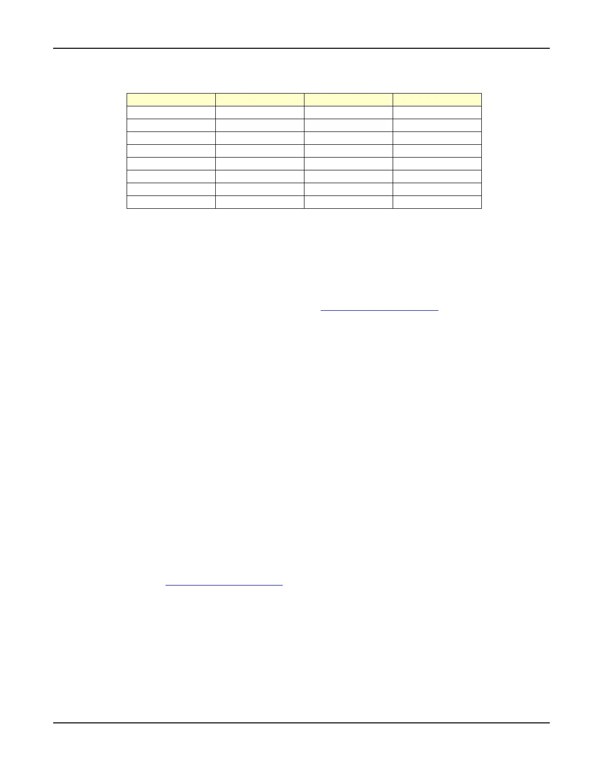
Test Connector pin types are as follows:
Routine Safety Testing and Inspection
The following electrical tests and inspection information is provided for guidance purposes only. These
tests involve the use of voltages and currents that can cause injury and should only be performed by
qualified personnel familiar with ESD and electrical safety precautions.
Prior to carrying out any inspection or test procedure, disconnect all external equipment from the Test
Set and disconnect the Test Set from the AC Power Supply. All tests should include the instrument’s
own supply lead, all covers must be fitted and the 3900 AC Power Supply Switch
must be in the ON
position.
Recommended tests and inspection should be carried out in the following sequence:
● Visual Inspection
● Earth (Ground) Bonding Tests
● Insulation Resistance Test
Visual Inspection
Visual inspections should be performed periodically depending on operating environment, maintenance
and use.
As a guide, visual inspection should include the following when appropriate:
● Verify Test Set has been installed in accordance with the instructions provided (e.g., that
ventilation is adequate, supply isolators are accessible, supply wiring is adequate and properly
routed).
● Ensure that AC Power Cord and supply connector(s) are in good condition.
● Verify the correct rating and type of supply fuses are used.
● Examine the stability and condition of covers and handles.
● Check the presence and condition of all warning labels and markings and supplied safety
information.
● Check the wiring in re-wireable plugs and appliance connectors.
● Check the cleanliness and condition of any ventilation fan filters.
● Ensure that the AC Power Supply Switch
isolates the equipment from the AC Power Supply.
● Check the supply indicator functions (if fitted).
Any noted defects should be corrected before proceeding with the following electrical tests.
Pin Number Signal Type Pin Number Signal Type
1 Digital In 1 9 Digital Out 1
2 Digital In 2 10 Digital Out 2
3 Digital In 3 11 Digital Out 3
4 Digital In 4 12 Digital Out 4
5 Digital In 5 13 Serial Out
6 No Connection 14 No Connection
7 Ground 15 Ground
8 PGM V+ Out