Radio Test Instruments
Subject to Export Control, see Cover Page for details.
7-15
Oscilloscope
The Oscilloscope provides a two channel oscilloscope for examining AF waveforms. Input signals
can be routed from the CH1 and CH2 Connectors to either Trace A or Trace B trace options. Refer
to the 3900 Platform Specifications for the Oscilloscope’s operating parameters.
Basic Settings
The Oscilloscope can be viewed in minimized or maximized view when it is selected from a Test
Measurement menu.
The Source and Coupling can be set differently for each trace. The second row of data at the top of
the Tile shows the Trace Trigger settings. These settings are accessed by pressing the [Trigger]
Soft Key. Auto or Normal modes of triggering can be selected and configured to respond to a rising
or falling input voltage.
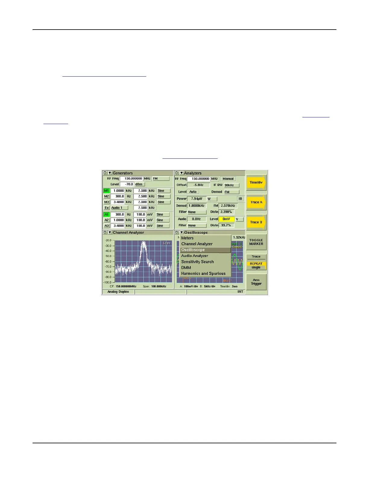
Accessing the Oscilloscope
The Oscilloscope is accessed from the drop-down menu on the System Test Measurements Tiles
(refer to Fig. 7-17). Refer to Chapter 3, Test Set Operation
for information on accessing system
menus.
Fig. 7-17 Accessing the Oscilloscope