Installation
Subject to Export Control, see Cover Page for details.
2-7
GPIB Connector pin functions are as follows:
See also GPIB/IEEE-488 Interface Connection
in Chapter 3, Test Set Operation.
Stacked Connectors
When stacking connectors to make multiple connections, ensure that excessive strain is not placed
on the GPIB socket; strain can damage the GPIB Connector, resulting in intermittent or faulty
connections.
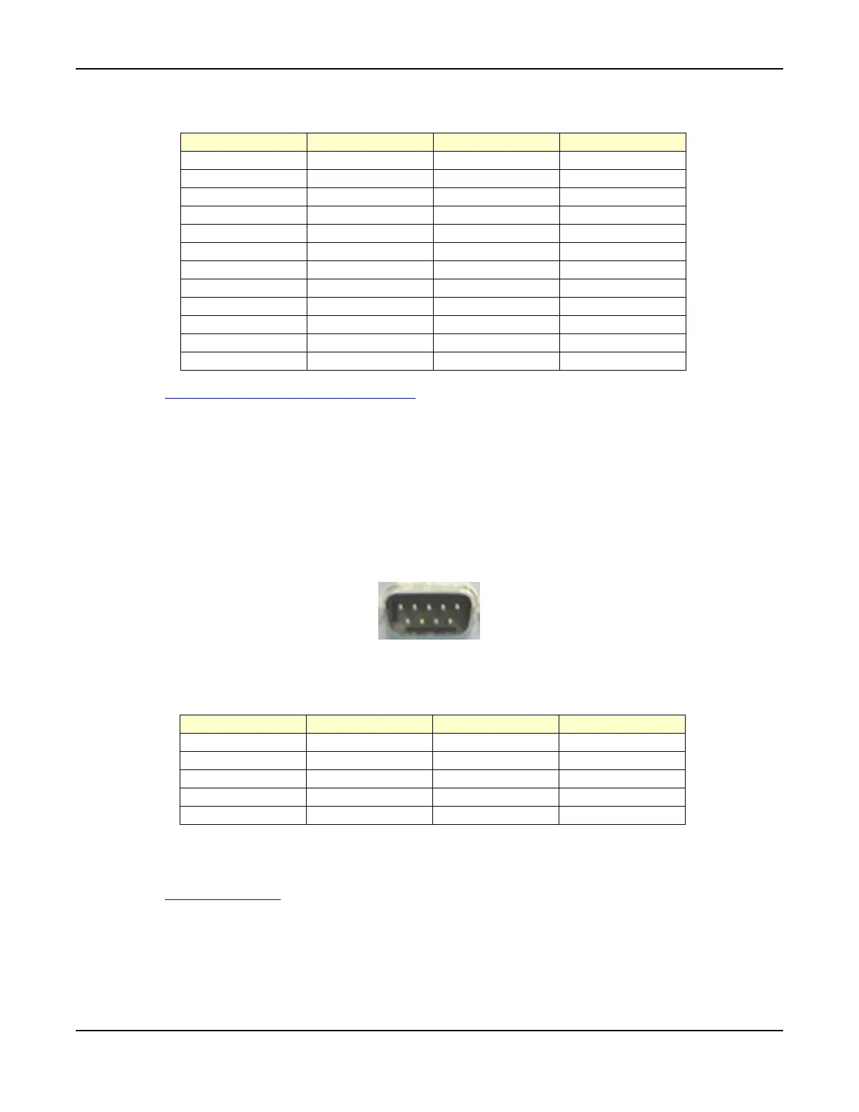
Serial Connector
The Serial Connector is an RS-232 Data Terminal Equipment (DTE) with a 9-way D-type plug
mounted on the rear panel. Refer to Fig. 2-7 for pin locations. Software to support specific radios is
planned for future software releases.
Fig. 2-7 Serial Connector Pin Locations
Serial Connector pin functions are as follows:
Functions DTR on contact 4 and RTS on contact 7 are held at logic 1. When connecting the Test Set
to another DTE device, such as a PC, a NULL MODEM cable is required. Hard handshaking is not
implemented.
See also Serial Connector
in Chapter 3, Test Set Operation.
Pin Number Function Pin Number Function
1 Data I/O 1 13 Data I/O 5
2 Data I/O 2 14 Data I/O 6
3 Data I/O 3 15 Data I/O 7
4 Data I/O 4 16 Data I/O 8
5EOI17REN
6 DAV 18 Pair with 6
7 NRFD 19 Pair with 7
8 NDAC 20 Pair with 8
9 IFC 21 Pair with 9
10 SRQ 22 Pair with 10
11 ATN 23 Pair with 11
12 Ground Shield 24 Logic Ground
15
6
9
Pin Number Function Pin Number Function
1 DCD 6 DSR
2 Rx Data In 7 RTS
3Tx Data Out8 CTS
4DTR9 RI
5 Ground