Subject to Export Control, see Cover Page for details.
3-1
Chapter 3
Test Set Operation
Introduction
Unless specifically mentioned, this chapter refers to local operation of a 3900 configured with factory
default settings. New Test Sets are configured to start in the factory default setting. Before using Test
Set, review power requirements and powering up procedure described in Chapter 2, Installation
. This
chapter describes the following:
● Identification and operation of 3900 connectors and power inputs.
● Screen layout, Tile navigation and selecting and entering data.
● Use soft keys and their associated menus.
Powering On
To power on the Test Set:
1. Complete installation instructions as defined in Chapter 2, Installation
.
2. Connect the Test Set to the AC Power Supply.
3. Turn the AC Power Supply Switch on the rear panel to the ON position. The LED above the On/
Standby Key turns RED. Press the On/Standby Key to power on the Test Set.
4. Verify no error messages appear on the display during power-up process. The Factory Default
Screen (refer to Fig. 3-1) should appear at initial start-up; this screen is not displayed again
during the power-up process unless the Restore Factory Defaults procedure is completed (refer
to Restoring Factory Default State).
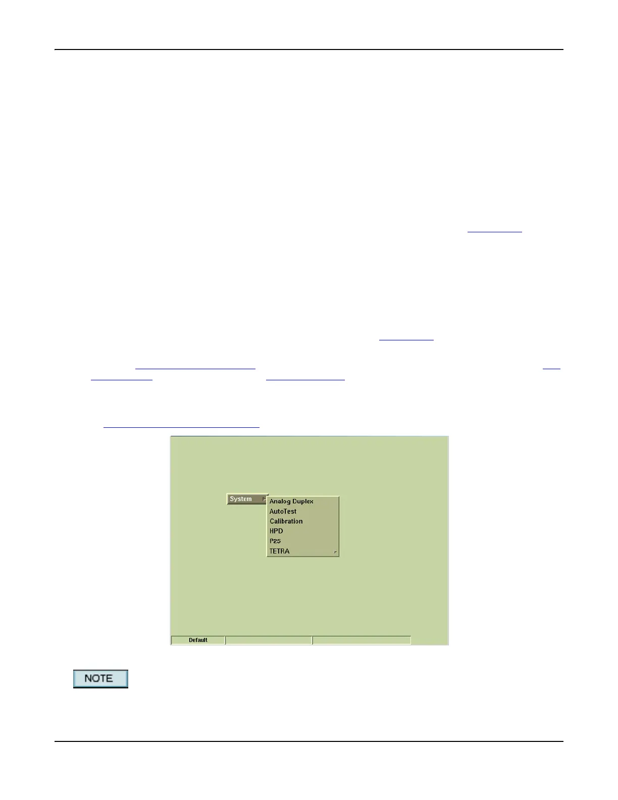
Fig. 3-1 Factory Default Tile
System menu contents vary according to the options installed in the Test Set.