Test Set Operation
Subject to Export Control, see Cover Page for details.
3-7
Display HOLD Key
The Hold Key freezes the display to allow the user to capture and save the current screen
display. Refer to the section titled Display Hold Tile
for use of this feature.
On/Standby Key
The Power Supply On/Standby key is referred to as the On/Standby key. The Test Set should
always be powered down using the On/Standby Key before disconnecting the AC Power Supply
from the Test Set. This key is active when the associated LED is illuminated.
If the On/Standby Key LED is not illuminated, the Test Set is OFF. Place the AC Power Supply
Switch on the rear panel to the ON position to place the Test Set in STANDBY mode.
If the On/Standby LED is ORANGE, the Test Set is in STANDBY mode. Pressing the On/Standby
Key initiates the Power-up sequence, returning the Test Set to the operating state it was in when
unit was last powered down.
During the Power-up sequence, pressing the On/Standby Key when the LED is BLUE stops the
Power-up sequence and returns the Test Set to Standby mode.
When the Test Set is operating the On/Standby LED is GREEN.
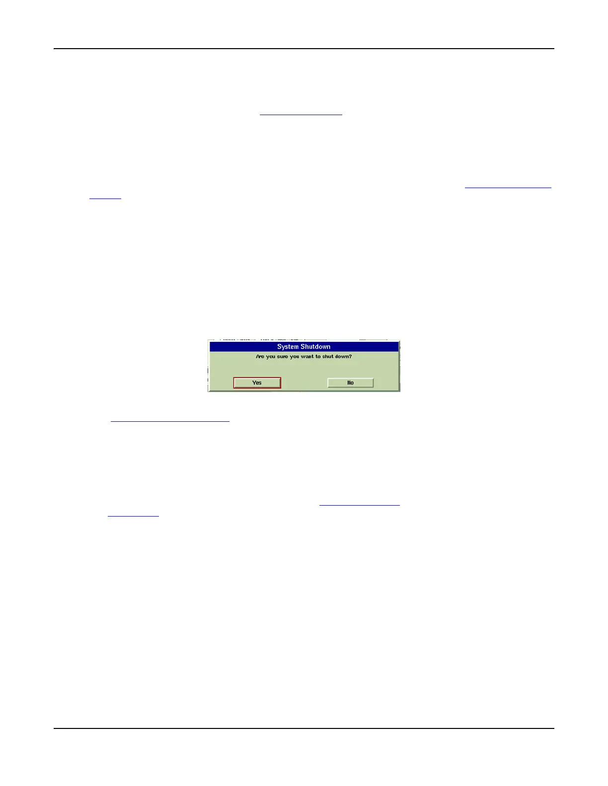
Pressing the On/Standby Key displays a dialog box (shown in Fig. 3-4) requesting confirmation
to shut down Test Set. Selecting YES or pressing the On/Standby Key again initiates the Power-
down sequence, saving all current settings and results and placing the Test Set in Standby
mode. Selecting NO aborts the Power-down sequence and the Test Set continues operating and
any ongoing testing is unaffected.
Fig. 3-4 System Shut-Down Prompt Dialog Box
The AC Power Supply Switch
isolates the Test Set from the AC power supply. Disconnect the
power supply cable from the AC power supply to remove the Test Set from AC power supply.
3.5 inch Floppy Disk Drive
The Floppy Disk Drive is only available on the 3901 and 3902.
The 3.5 inch floppy disk drive provides an interface to the Test Set for downloading data,
settings and captured display files. Stored settings and data can also be loaded into the Test
Set. These features are controlled through the Store/Recall Tile
which is accessed by pressing
the UTILS Key
.
Powering Up
Before powering up the Test Set, check that the floppy disk drive does not contain a disk. If
there is a disk in the drive at power up the Test Set may display irrelevant error messages. If
this occurs, remove the disk and restart the Test Set.
Digital Multimeter
The Digital Multimeter (DMM) Option (390XOPT035) is only available on the 3920. 3901 and
3902 Test Sets may be upgraded to this option.
The DMM (Digital Multimeter) Tile provides users with the ability to perform resistance
measurements and AC and DC current and voltage measurements.