Radio Test Instruments
Subject to Export Control, see Cover Page for details.
7-16
Oscilloscope Tile Layout
The Oscilloscope, referred to as the Scope, can be viewed in minimized and maximized view.
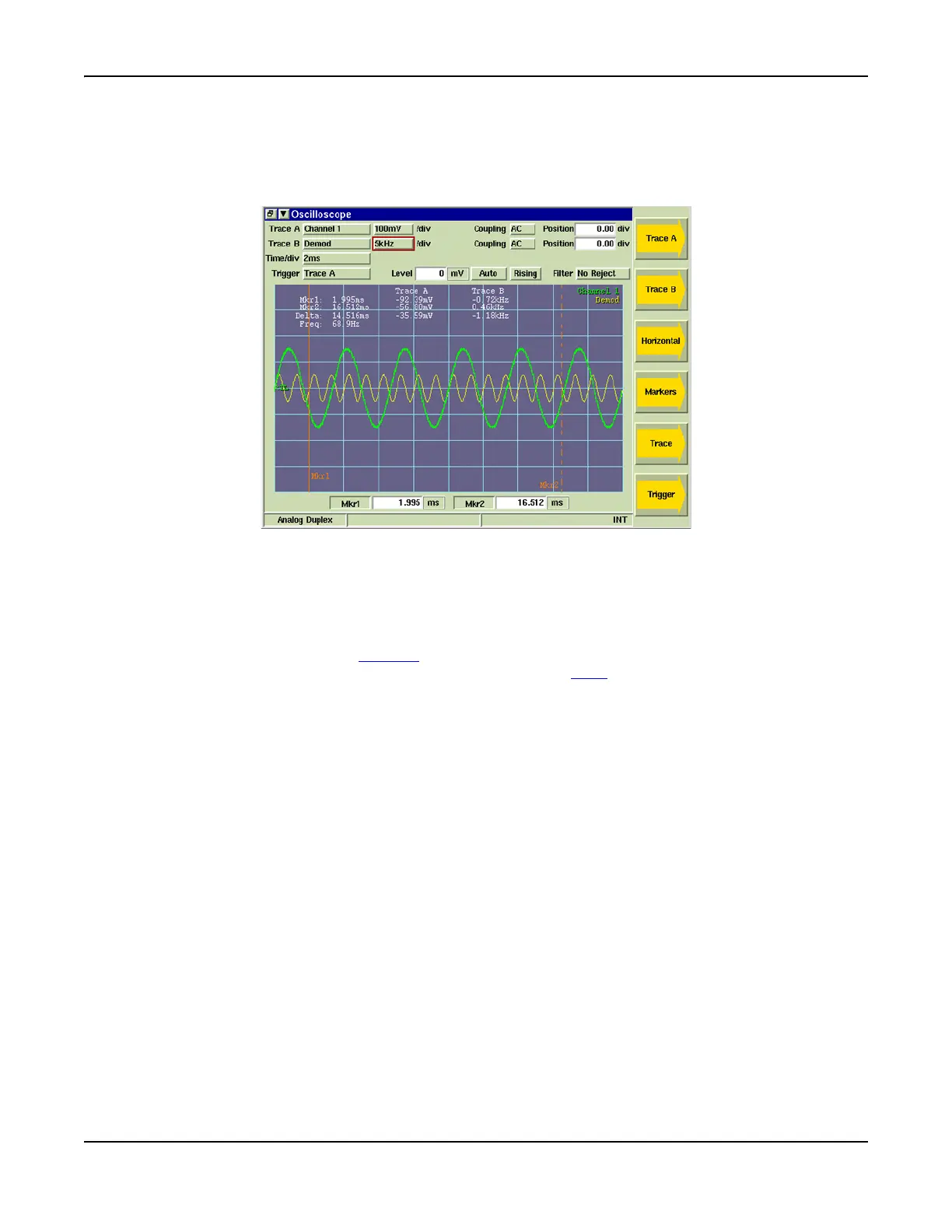
Fig. 7-18 shows the maximized view of the Scope. Fig. 7-25 shows the Scope when minimized. Note
that the Soft Keys change between maximized and minimized views.
Fig. 7-18 Oscilloscope Tile - Maximized View
Field/Soft Key Definitions
Trace A / Trace B
These soft keys access additional soft keys that adjust scaling and positioning of Trace A and
Trace B. The up/down arrow keys move the signal trace up or down on the display,
simultaneously adjusting the Position value. The [Expand / Contract] Soft Keys adjust the height
of the signal trace, which can also be changed using the n/
div drop-down menu.
n/div
Drop-down menu selects the vertical scale of the trace. The scale can also be increased or
decreased using the [Expand / Contract] Soft Keys. The scale unit of measurement changes
according to type of measurement being performed (refer to Fig. 7-19).
Coupling
Selects how the signal is connected to the Test Set.
AC: Signal is connected to the Test Set through a capacitor that removes the CD component.
DC: Signal is connected directly to the Test Set.
GND: Signal is grounded; GND is typically used to set a reference.
Position
Adjusts vertical position of trace on the display field.
Time /div
The Time/div drop-down menu sets the Scope’s timebase repetition. The timebase repetition
rate setting can be increased or decreased by using the [Expand] or [Contract] Soft Keys.