Radio Test Instruments
Subject to Export Control, see Cover Page for details.
7-17
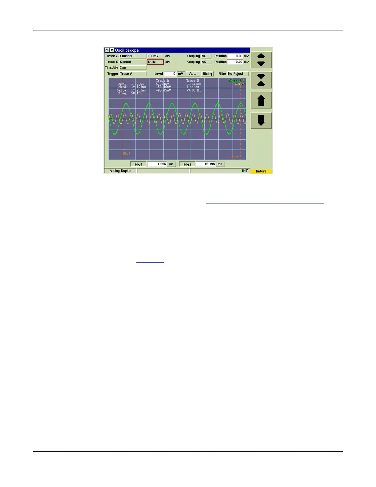
Fig. 7-19 Oscilloscope Tile - Vertical Settings
Trigger
Selects Trigger source as Trace A, Trace B or the External Trigger Signal Input Connector.
Level
Sets a voltage or percent value for the trace trigger level. The trigger level point is indicated by
a green TL flag on the left of the display.
Auto/Normal
Selects the Trigger mode of operation. When NORMAL is selected the trace is triggered when
the trace passes through the Trigger Level value. When AUTO is selected the trace 'free runs' at
the rate determined by the Time /div setting.
Rising/Falling
When RISING is selected the trace triggers when the trace passes the trigger set level as it
increases in value. When FALLING is selected the trace triggers when the traces passes the
trigger set level as it decreases in value.
Filter
Selects amount of noise, if any, to be filtered from the trigger path.
No Reject: No noise is filtered from trigger path.
Noise Reject: Filters medium level noise from trigger path.
HF Reject: Filters High Frequency noise from trigger path.
Mkr1 / Mkr2
Toggle buttons enable Marker 1 and Marker 2. When Markers are enabled, marker data fields
can be edited to define marker position. Refer to section titled [Markers] Soft Key
for additional
information on configuring markers.