40 1220 Infinity II LC System User Manual
3
Installation
Installing the Hardware
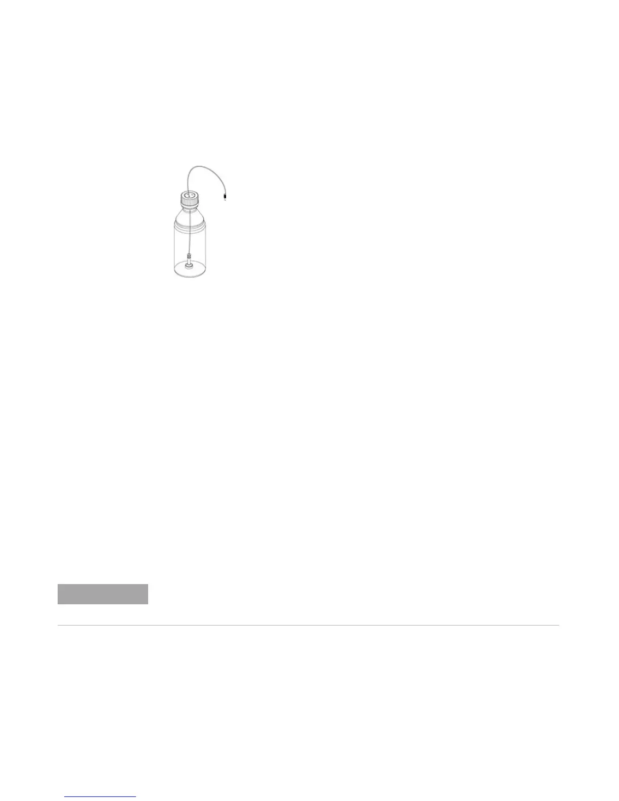
6 Place the Solvent Inlet Filter end of the Bottle Head Assembly in the Solvent
Bottle (see picture below).
Figure 4 Bottle Head Assembly and Solvent Bottle
7 Prime the tubing using the Syringe (9301-044) and Syringe adapter
(9301-1337) (part of the Accessory kit) until the tubing is completely filled
with water.
8 Connect the Bottle Head Assembly connector (see Figure 4 on page 40 Item
1+2) to:
• the passive inlet valve (isocratic pump) or
• the degasser inlet Channel A (gradient pump).
9 Connect the waste tube with the fitting attached (part of Accessory Kit) to
the flow cell outlet and the other end to an appropriate solvent waste
container (see Figure 5 on page 41).
10 Attach the corrugated waste tube (part of Accessory Kit) to the VWD leak
tray outlet adapter and guide it to a proper waste container (see Figure 5 on
page 41).
11 Connect the waste tube (part of Accessory Kit) to the purge valve outlet
adapter and the other end to the waste container.
12 Connect the network connection between the instrument and your PC.
13 Verify that the power push button at the front of the module (see Figure 5
on page 41) stands off. Now connect the power cord to the instrument and
the power line.
)HUUXOHVZLWKORFNULQJ
7XEHVFUHZ
:LUHPDUNHU
6ROYHQWWXELQJP
)ULWDGDSWHUSDFNRI
6RYHQWLQOHWILOWHUP
More details about how to establish a network connection to the instrument can be found
in “Connecting the Agilent 1220 Infinity II LC to the PC” on page 45 or “LAN
Configuration” on page 59

 Loading...


