Inlets and valves
6850
6850
Released: April 2004 6850 Series Gas Chromatograph Service Procedures 127
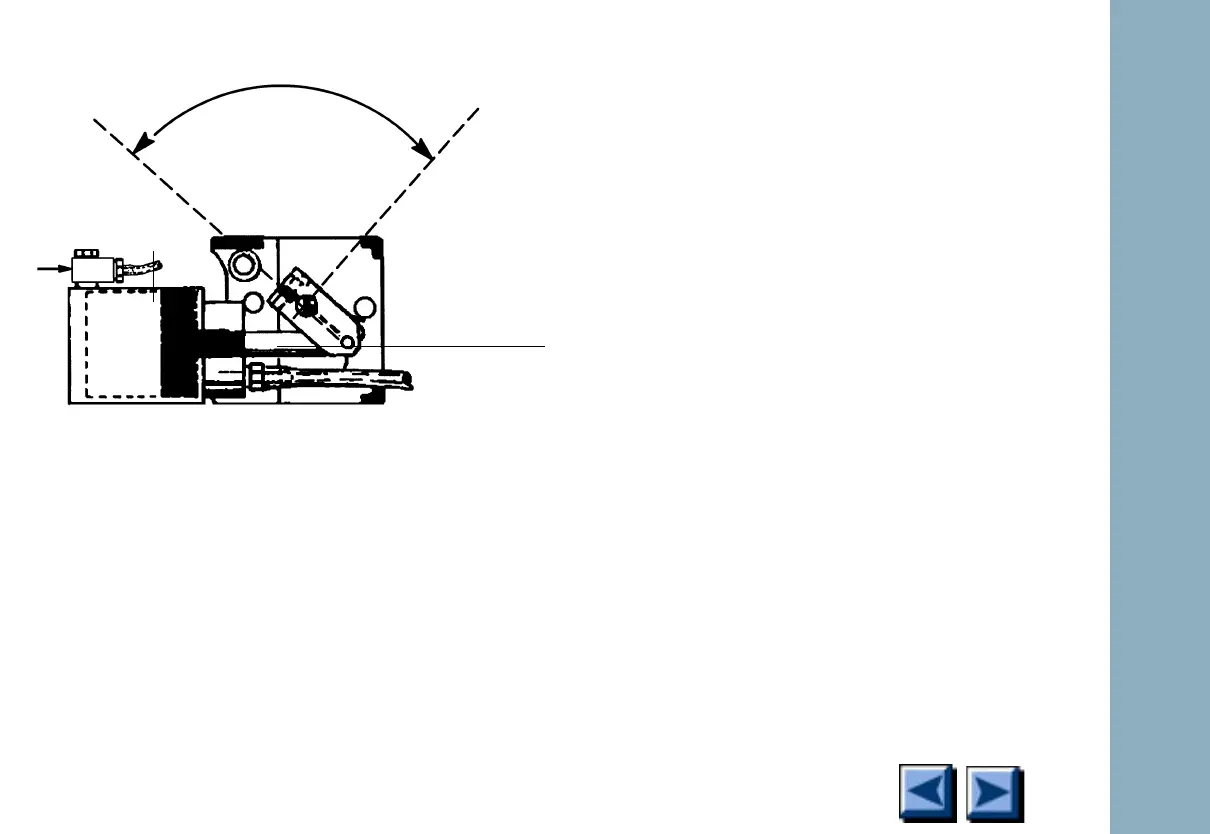
Figure 1-47. Actuator in the fully extended
position
6. If variable restrictors are present, remove
their mounting hardware in the following
order: two Torx T-20 screws, hex nut, and
mounting bracket for each restrictor valve.
7. Remove the two Torx T-20 screws securing
the valve box top assembly to the standoffs.
Lift the valve box top assembly straight off
the valve box. Be careful not to move the
valve rotor index pin from its “at rest” posi-
tion.
NOTE: If valve/actuator alignment is to be made,
see Valve/Actuator Alignment in this section.
8. To reassemble: Align the two mounting holes
in the valve box top assembly with the stand-
offs in the valve box. Lower the box top
assembly until it rests on the standoffs.
9. Secure the valve box top assembly with two
Torx T-20 mounting screws. Tighten these
screws firmly. Reinstall hardware for vari-
able restrictors if present.
10. Exercise the valve(s) on and off a few times
to verify operation.
90°Max
Cylinder
Piston rod
(extended
Piston
position)

 Loading...


