Inlets and valves
6850
6850
Released: April 2004 6850 Series Gas Chromatograph Service Procedures 78
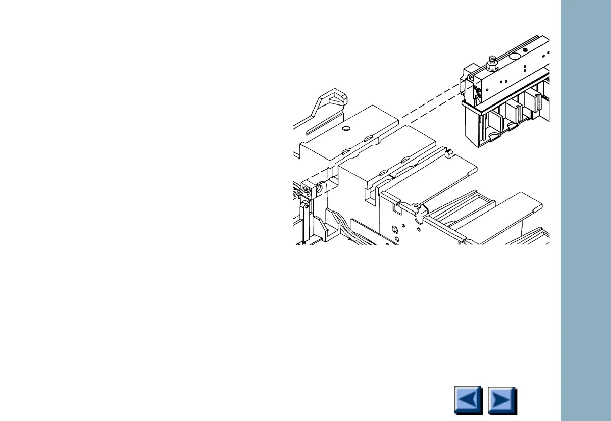
3. Unclip the heater/sensor leads from the con-
nector to the left of the inlet carrier.
4. Disconnect the inlet plumbing and reroute
the plumbing from underneath the tabs on
the left side of the instrument.
EPC inlets: The inlet plumbing terminates in
a pneumatics block connected to the EPC
flow module with one Torx T-10 screw.
Non-EPC inlets: The inlet plumbing is
located in the manual inlet side carrier. The
tubing labelled “C” is connected to the
Forward Pressure Regulator. The line
labelled “P” is connected to the septum
purge regulator.
Figure 1-20. Disconnecting the inlet
plumbing block (EPC inlets)
New?

 Loading...


