121
Maintenance and Repair
Exchanging the SPM Board
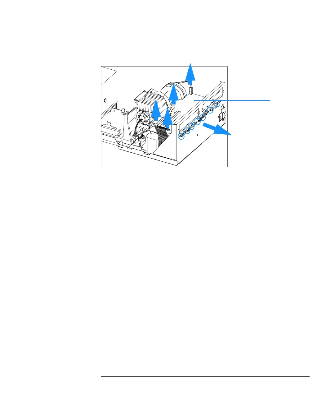
Figure 37 Removing Connectors and Screws from SPM Board
5 Unscrew two screws each, at the GPIB connector, at the APG remote
connector and at the multicell connector and remove the SPM board.
Replacing the SPM Board
1 Position the SPM board on the middle rear foam block.
2 Connect the connector from the power supply to the SPM board (right), the
flat ribbon cables from the SDA and LPS boards which are above each other,
the shutter cable and the fan cable, see Figure 37.
3 Fix two screws each, at the GPIB connector, at the APG remote connector and
at the multicell connector.
4 Replace the upper rear foam block.
5 If available, replace any accessory board or MIO board (plugged in from the
rear side of the instrument).
6 Replace the plastic and sheet metal rear cover. Push the plastic rear cover
down so that it locates on both sides, see “Removing and Replacing Covers”
on page 109.
7 Reconnect line power and turn on the instrument. Check that the
spectrophotometer passes its self-test, this means that the green light on the
front panel comes on and that you can do a blank measurement from your
software.
SPM board

 Loading...


