Spectrum Analyzer Measurements 3-7 Setting Trace Parameters
Spectrum Analyzer MG PN: 10580-00447 Rev. H 3-27
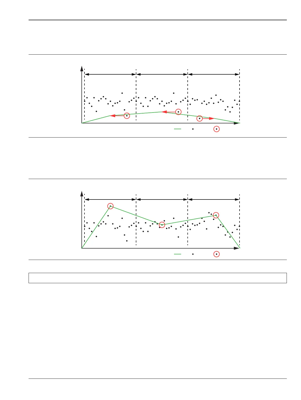
Negative
Shows the minimum amplitude of sampled data for each display point. This method is also useful when
measuring modulated signals to see if some frequencies are not being used.
Sample
Shows the transient amplitude of the center of sampled data for each display point. This method is useful when
measuring low-level signals and noise measurements. Only available in zero span and RSSI measurements.
Figure 3-18. Negative Detector Type
Figure 3-19. Sample Detector Type
Note When Sample detector is selected, all traces must use sample detection.
Frequency/Time
Negative Detection
Odd Display Point Sampling Interval
Amplitude
Even Display Point Sampling Interval Odd Display Point Sampling Interval
Selected Data PointData PointTrace
Frequency/Time
Sample Detection
Odd Display Point Sampling Interval
Amplitude
Even Display Point Sampling Interval Odd Display Point Sampling Interval
Selected Data PointData PointTrace