14-2
Chapter 14. Specifications
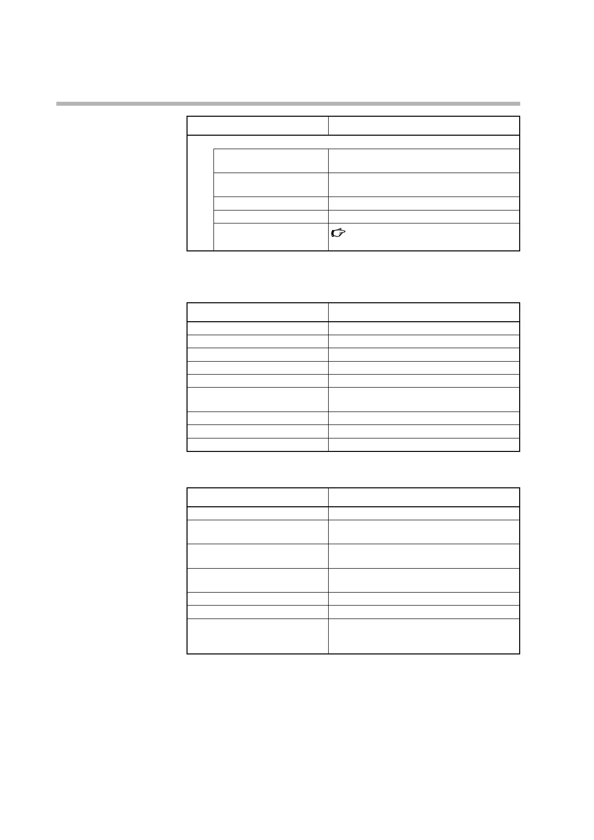
Item Description
DC current
DC current type 0–20 mA
4–20 mA
Indication accuracy (under
standard conditions)
±0.2 % FS ±1 digit
Allowable input* 30 mA or less, or 4 V or less
Input impedance 100 Ω max. (with 20 mA input)
Operation upon input wire
burnout
Operation when a PV input error occurs
(p.11-4)
* A voltage or current input greater than the allowable input may damage the circuits.
z
Digital input (DI1–2) (optional)
Item Description
Number of inputs 2
Input type Non-voltage contacts or open collector
Allowable ON contact resistance 250 Ω max.
Allowable OFF contact resistance 100 kΩ min.
Allowable ON residual voltage 1.0 V max.
Terminal current while ON Approx. 7.5 mA (when shorted) / approx. 5.0 mA
(at a contact resistance of 250 Ω)
Minimum hold time Sampling cycle + 10 ms
Open terminal voltage 5.5 V DC ±1 V
Parallel connection circuit voltage 24 V DC max.
z
Current transformer inputs (CT1–2) (optional)
Item Description
Number of inputs 2
Input object Current transformer with 100–4000 turns
(availability is in 100-turn units)
Measurement current 0.4–50.0 A AC, 50/60 Hz (800 turns, 1 power wire
pass)
Allowable measured current 0.0–70.0 A AC and peak current 110 A (800 turns,
1 power wire pass)
Indication accuracy ±5 % FS ±1 digit (CT accuracy is not included)
Indication resolution 0.1 A AC
Precautions when using a CT Pass the wire carrying the heater current through
the CT.
Do not use CT input for phase control.