MAX Operation & Service Manual 129MAX Operation & Service Manual Section 6: Maintenance & Service 129
5. Place adjustment tool (mounted inside the lane machine in front of the electronics enclosure)
across the rear wheel and drive wheel on the 7-pin side of the machine. Refer to Figure6-19.
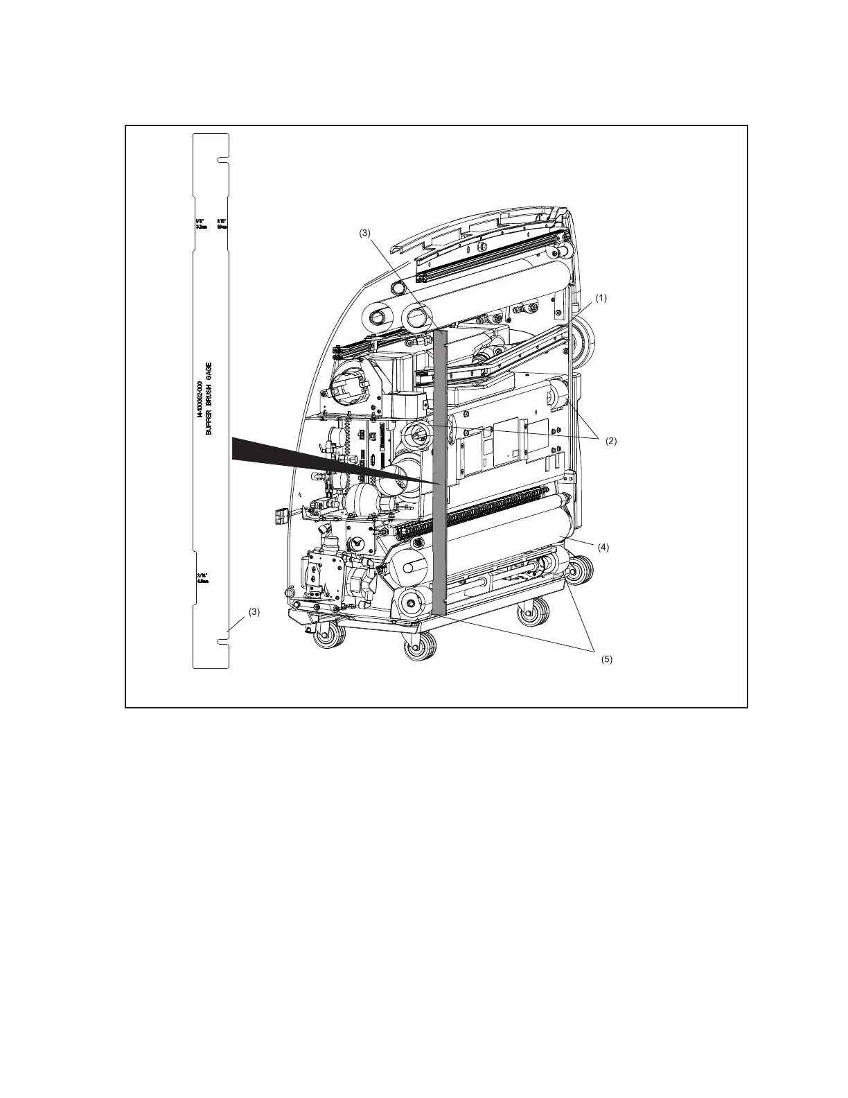
Figure6-19.AdjustmentTool-SectionView
(1) SQUEEGEE/VACUUM HEAD ASSEMBLY
(2) TRACTION DRIVE WHEELS
(3) BUFFER/SQUEEGEE ADJUSTMENT
TOOL
(4) BUFFER BRUSH
(5) REAR SHAFT WHEELS
6. Verify that the desired adjustment notch is sitting over the buffer brush (the buffer brush is set at
the factory with the 1/16” notch).
7. To raise the buffer brush, move the motor position in the slots toward the front of the machine.
8. To lower the buffer brush, move the motor position in the slots toward the rear of the machine.
9. When the brush is in desired position, snug two of the three mounting bolts using the 3/8”
socket wrench.
10. Verify adjustment on 7-pin side of machine, then check the adjustment across the rear and drive
wheels on the 10-pin side of the machine.