MAX Operation & Service Manual 157MAX Operation & Service Manual Section7:Troubleshooting157
The Conditioning System
1. The machine applies conditioner directly to the lane surface in a pattern specied by the user.
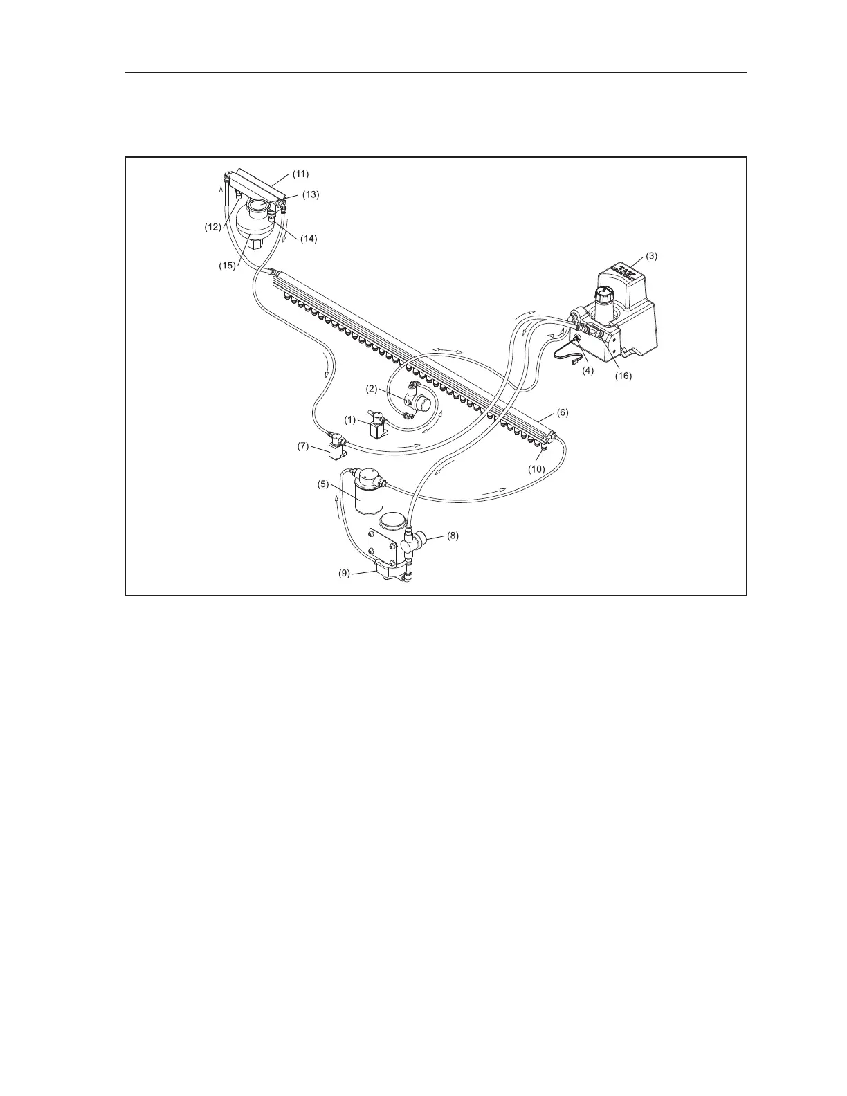
Refer to Figure 7-5.
Figure7-5.ConditioningSystem
(1) CONDITIONER VENT VALVE
(2) CONDITIONER OVERFLOW
RESERVOIR
(3) CONDITIONER SUPPLY TANK
(4) CONDITIONER LEVEL FLOAT SENSOR
(5) CONDITIONER SPIN-ON FILTER
(6) INJECTOR RAIL ASSEMBLY
(7) CONDITIONER PRESSURE CONTROL
VALVE
(8) CONDITIONER SCREEN FILTER
(9) CONDITIONER PUMP
(10) CONDITIONER INJECTOR
(11) ACCUMULATOR R AIL
(12) CON DITI ON ER TEMPERATU RE
SENSOR
(13) CONDITIONER PRESSURE GAUGE
(14) CONDITIONER PRESSURE SENSOR
(15) ACCUMULATOR
(16) OIL CONTAMINATION SENSOR
a. 39 injectors mounted in a pressurized rail apply conditioner directly onto the lane surface.
b. The rail is xed (i.e. the injectors do not reciprocate from side to side) to avoid creating a
zigzag conditioner pattern on the bowling lane.
c. Each injector disperses uid across the approximate width of one board of the lane and is
independently controlled based on the conditioning pattern selected.
d. Injectors pulse every 0.1 feet (30.5 mm) (pulse pattern is distance based, not dependent on
machine’s rate of travel).
e. The pressure of the conditioning system is set before conditioning the rst lane as
described previously in this section, “Preparing for Operation”. The pressure of the
conditioning system is then reset as soon as the lane machine returns to the foul line so it is
ready for the next lane.