MAX Operation & Service Manual 211MAX Operation & Service Manual Section9:Appendix211
ELECTRICAL SCHEMATICS & DIAGRAMS
The following schematics and diagrams are provided for your reference:
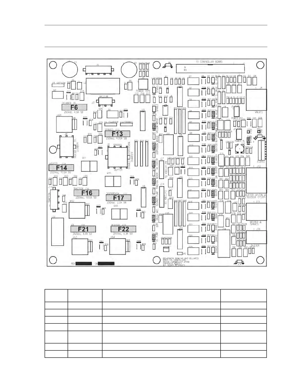
Fuse Locations & Specications and Output LED Locations
Figure9-1.FuseandLEDLocations
Fuses
Location
ID
Part No. Description Application
F6 14-860214-000 Pkg. of 5 Fuses - 4.0A, 250V, 5 x 20 mm, Slow Blow Cleaner Pump
F13 14-860214-000 Pkg. of 5 Fuses - 4.0A, 250V, 5 x 20 mm, Slow Blow Spare
F14 14-860216-000 Pkg. of 5 Fuses - 10A, 250V, 5 x 20 mm, Slow Blow Conditioner Heater
F16 14-860216-000 Pkg. of 5 Fuses - 10A, 250V, 5 x 20 mm, Slow Blow Traction Drive Motor
F17 14-860242-000 Pkg. of 5 Fuses - 2.0A, 250V, 5 x 20 mm, Slow Blow Dispersion Roller
Motor
F21 14-860214-000 Pkg. of 5 Fuses - 4.0A, 250V, 5 x 20 mm, Slow Blow Conditioner Pump
F22 14-860218-000 Pkg. of 5 Fuses - 6.3A, 250V, 5 x 20 mm, Slow Blow Buffer Drive Motor
FuseSpecicationchart